
Battery-Powered Motor Control System with L298N and Pushbuttons
View and Edit Project In Cirkit Designer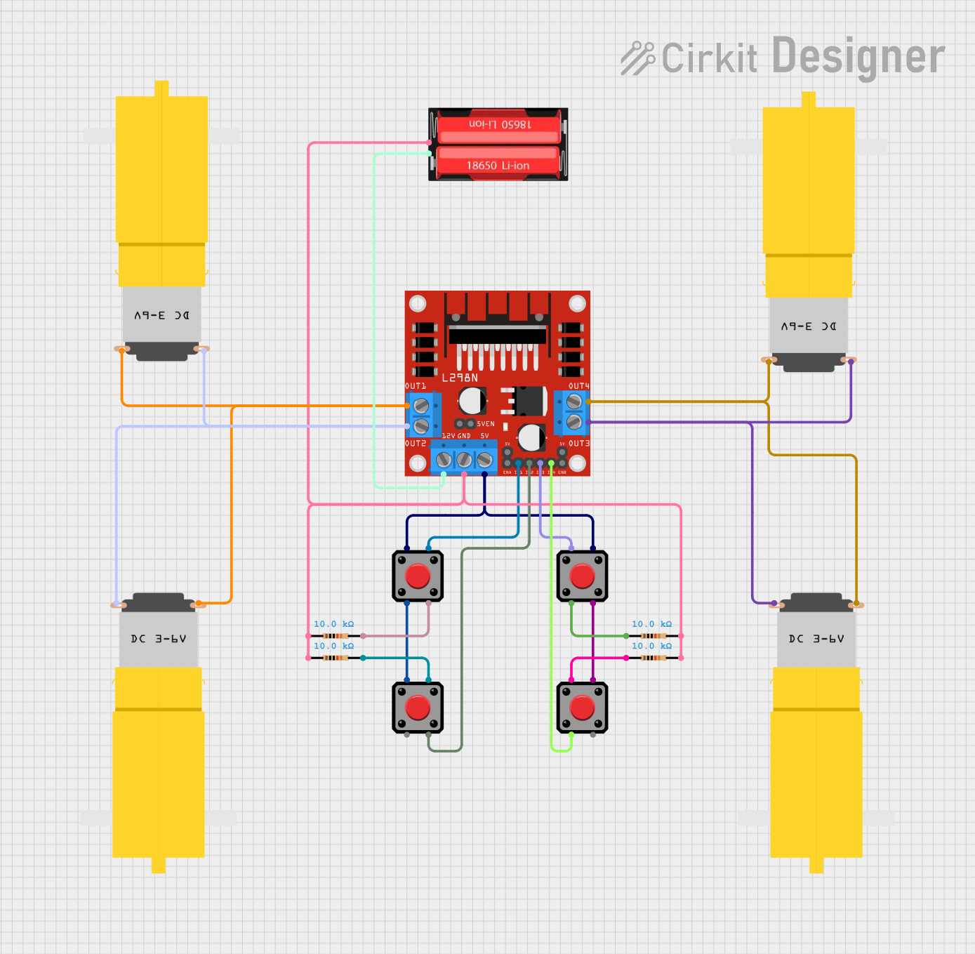
Circuit Documentation
Summary
This circuit is designed to control multiple DC motors using an L298N motor driver and pushbuttons. The circuit is powered by a 18650 Li-Ion battery. The pushbuttons are used to control the inputs of the L298N motor driver, which in turn controls the motors. Resistors are used for pull-down purposes to ensure proper logic levels at the inputs.
Component List
L298N DC Motor Driver
- Description: A dual H-bridge motor driver that allows control of the speed and direction of two DC motors.
- Pins: OUT1, OUT2, 12V, GND, 5V, OUT3, OUT4, 5V-ENA-JMP-I, 5V-ENA-JMP-O, +5V-J1, +5V-J2, ENA, IN1, IN2, IN3, IN4, ENB
Pushbutton
- Description: A simple pushbutton switch used to provide user input.
- Pins: Pin 1, Pin 2, Pin 3, Pin 4
Resistor
- Description: A 10k Ohm resistor used for pull-down purposes.
- Pins: pin1, pin2
- Properties: Resistance = 10k Ohms
Motor amarillo motorreductor hobby
- Description: A small DC motor with a gearbox for hobby projects.
- Pins: vcc, GND
18650 Li-Ion Battery
- Description: A rechargeable lithium-ion battery.
- Pins: Positive, Negative
Wiring Details
L298N DC Motor Driver
- OUT1 is connected to the vcc pins of two motors.
- OUT2 is connected to the GND pins of two motors.
- 12V is connected to the Positive pin of the 18650 Li-Ion battery.
- GND is connected to the Negative pin of the 18650 Li-Ion battery and to the pin2 of a resistor.
- OUT3 is connected to the GND pins of two other motors.
- OUT4 is connected to the vcc pins of two other motors.
- 5V is connected to Pin 1 of one pushbutton and Pin 4 of another pushbutton.
- IN1 is connected to Pin 4 of a pushbutton.
- IN2 is connected to Pin 3 of another pushbutton.
- IN3 is connected to Pin 1 of another pushbutton.
- IN4 is connected to Pin 2 of another pushbutton.
Pushbuttons
Pushbutton 1
- Pin 1 is connected to 5V of the L298N motor driver.
- Pin 4 is connected to IN1 of the L298N motor driver.
- Pin 2 is connected to pin1 of a resistor.
- Pin 3 is connected to Pin 4 of another pushbutton.
Pushbutton 2
- Pin 1 is connected to Pin 4 of another pushbutton.
- Pin 4 is connected to 5V of the L298N motor driver.
- Pin 2 is connected to Pin 1 of another pushbutton.
- Pin 3 is connected to IN2 of the L298N motor driver.
Pushbutton 3
- Pin 1 is connected to IN3 of the L298N motor driver.
- Pin 2 is connected to Pin 1 of another pushbutton.
- Pin 3 is connected to Pin 4 of another pushbutton.
- Pin 4 is connected to pin2 of a resistor.
Pushbutton 4
- Pin 1 is connected to Pin 2 of another pushbutton.
- Pin 2 is connected to IN4 of the L298N motor driver.
- Pin 3 is connected to Pin 4 of another pushbutton.
- Pin 4 is connected to Pin 3 of another pushbutton.
Resistors
Resistor 1
- pin1 is connected to Pin 2 of a pushbutton.
- pin2 is connected to GND of the L298N motor driver.
Resistor 2
- pin1 is connected to pin2 of another resistor.
- pin2 is connected to Pin 3 of a pushbutton.
Resistor 3
- pin1 is connected to pin2 of another resistor.
- pin2 is connected to Pin 4 of a pushbutton.
Resistor 4
- pin1 is connected to pin2 of another resistor.
- pin2 is connected to Pin 1 of a pushbutton.
Motors
Motor 1
- vcc is connected to OUT1 of the L298N motor driver.
- GND is connected to OUT2 of the L298N motor driver.
Motor 2
- vcc is connected to OUT1 of the L298N motor driver.
- GND is connected to OUT2 of the L298N motor driver.
Motor 3
- vcc is connected to OUT4 of the L298N motor driver.
- GND is connected to OUT3 of the L298N motor driver.
Motor 4
- vcc is connected to OUT4 of the L298N motor driver.
- GND is connected to OUT3 of the L298N motor driver.
18650 Li-Ion Battery
- Positive is connected to 12V of the L298N motor driver.
- Negative is connected to GND of the L298N motor driver and to the pin2 of a resistor.
Code
There is no code provided for this circuit.