
Circuit Documentation
Summary of the Circuit
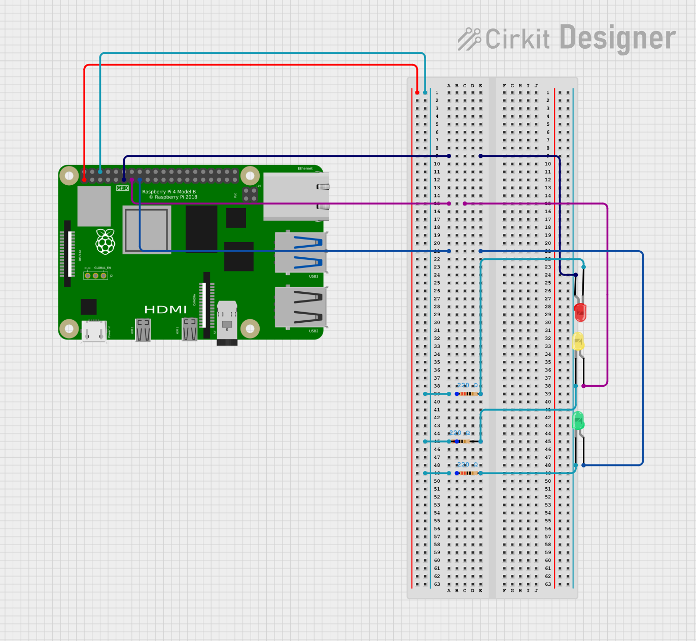
The circuit described in the provided inputs is designed to interface a Raspberry Pi 4B with three LEDs (red, yellow, and green). Each LED is connected to a GPIO pin on the Raspberry Pi through a current-limiting resistor. The purpose of this circuit is likely to provide visual indicators that can be controlled by the Raspberry Pi, potentially for status indication or simple output signaling.
Component List
Raspberry Pi 4B
- Description: A single-board computer with multiple GPIO pins for interfacing with various electronic components.
- Pins: 3V3, 5V, multiple GPIOs, GND, and others.
- Purpose: Acts as the main controller for the circuit, driving the LEDs via its GPIO pins.
LED: Two Pin (red)
- Description: A red light-emitting diode that emits red light when forward-biased.
- Pins: cathode, anode.
LED: Two Pin (green)
- Description: A green light-emitting diode that emits green light when forward-biased.
- Pins: cathode, anode.
LED: Two Pin (yellow)
- Description: A yellow light-emitting diode that emits yellow light when forward-biased.
- Pins: cathode, anode.
Resistor (220 Ohms)
- Description: A passive two-terminal electrical component that provides resistance to the flow of current.
- Pins: pin1, pin2.
- Properties: Resistance value of 220 Ohms.
Wiring Details
Raspberry Pi 4B
- 3V3: Not connected in this circuit.
- GND: Connected to the common ground net, which includes the cathodes of all LEDs through their respective resistors.
- GPIO17: Connected to the anode of the red LED.
- GPIO27: Connected to the anode of the yellow LED.
- GPIO22: Connected to the anode of the green LED.
LED: Two Pin (red)
- Cathode: Connected to the common ground net through a 220 Ohm resistor.
- Anode: Connected to GPIO17 on the Raspberry Pi 4B.
LED: Two Pin (green)
- Cathode: Connected to the common ground net through a 220 Ohm resistor.
- Anode: Connected to GPIO22 on the Raspberry Pi 4B.
LED: Two Pin (yellow)
- Cathode: Connected to the common ground net through a 220 Ohm resistor.
- Anode: Connected to GPIO27 on the Raspberry Pi 4B.
Resistor (220 Ohms)
- Pin1: Connected to the common ground net.
- Pin2: Connected to the cathode of one of the LEDs (red, green, or yellow).
Documented Code
No code was provided for the microcontrollers in the circuit. Typically, the code would be used to control the GPIO pins of the Raspberry Pi 4B to turn the LEDs on and off. Since no code is available, it is assumed that the user will develop their own software to control the LEDs via the Raspberry Pi's GPIO interface.