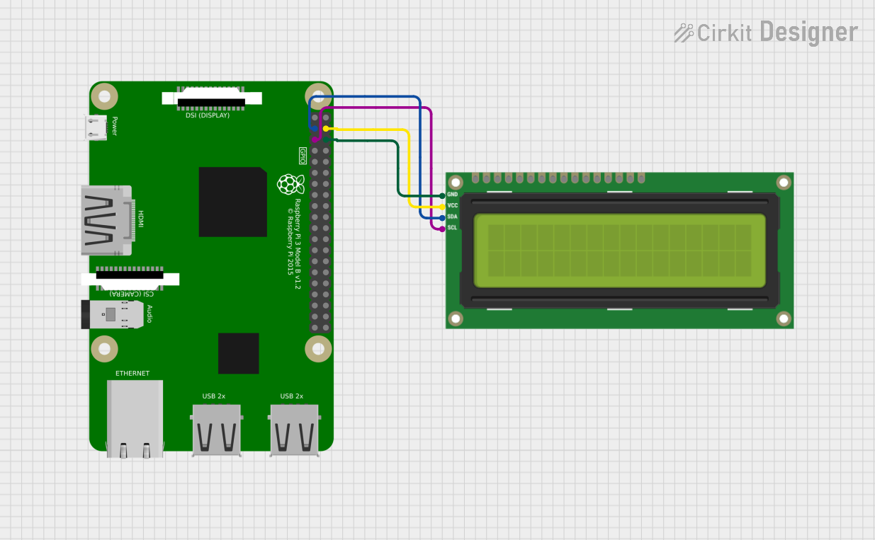
Raspberry Pi 3B Controlled I2C LCD Display

Circuit Documentation
Summary of the Circuit
This circuit consists of a Raspberry Pi 3B microcontroller board interfaced with an I2C LCD 16x2 screen. The Raspberry Pi 3B is responsible for controlling the display on the LCD screen via the I2C communication protocol. The I2C bus requires only two data connections, SDA (data line) and SCL (clock line), which simplifies the wiring and allows multiple devices to be connected to the same bus. The LCD screen is powered by a 5V supply from the Raspberry Pi, and the ground is shared between the two components.
Component List
Raspberry Pi 3B
- Description: A powerful microcontroller board based on the Broadcom BCM2837 SoC, featuring a quad-core ARM Cortex-A53 CPU and 1GB RAM.
- Pins: 40 GPIO pins including power, ground, and various communication interfaces.
- Purpose: Acts as the central processing unit of the circuit, running the software that controls the LCD screen.
I2C LCD 16x2 Screen
- Description: A 16-character by 2-line liquid crystal display that supports the I2C communication protocol.
- Pins: SCL, SDA, VCC (5V), GND, and additional pins for parallel interface and backlight control.
- Purpose: Displays information sent from the Raspberry Pi 3B.
Wiring Details
Raspberry Pi 3B
- SDA (Pin 3): Connected to the SDA pin of the I2C LCD screen for data transmission.
- SCL (Pin 5): Connected to the SCL pin of the I2C LCD screen to provide a clock signal.
- GND (Pin 6): Connected to the GND pin of the I2C LCD screen to provide a common ground reference.
- 5V (Pin 4): Connected to the VCC (5V) pin of the I2C LCD screen to power the display.
I2C LCD 16x2 Screen
- SDA: Connected to the SDA (Pin 3) of the Raspberry Pi 3B for data transmission.
- SCL: Connected to the SCL (Pin 5) of the Raspberry Pi 3B to receive the clock signal.
- VCC (5V): Connected to the 5V (Pin 4) of the Raspberry Pi 3B for power.
- GND: Connected to the GND (Pin 6) of the Raspberry Pi 3B to complete the power circuit.
Documented Code
Since no code was provided in the input, this section is not applicable for the current documentation. However, typically this section would include the source code for the microcontroller, along with comments explaining the functionality of the code and how it interacts with the connected components.