Cirkit Designer
Your all-in-one circuit design IDE
Home /
Project Documentation
ESP32 Battery Voltage Monitor with OLED Display and Touch Sensor
Circuit Documentation
Summary
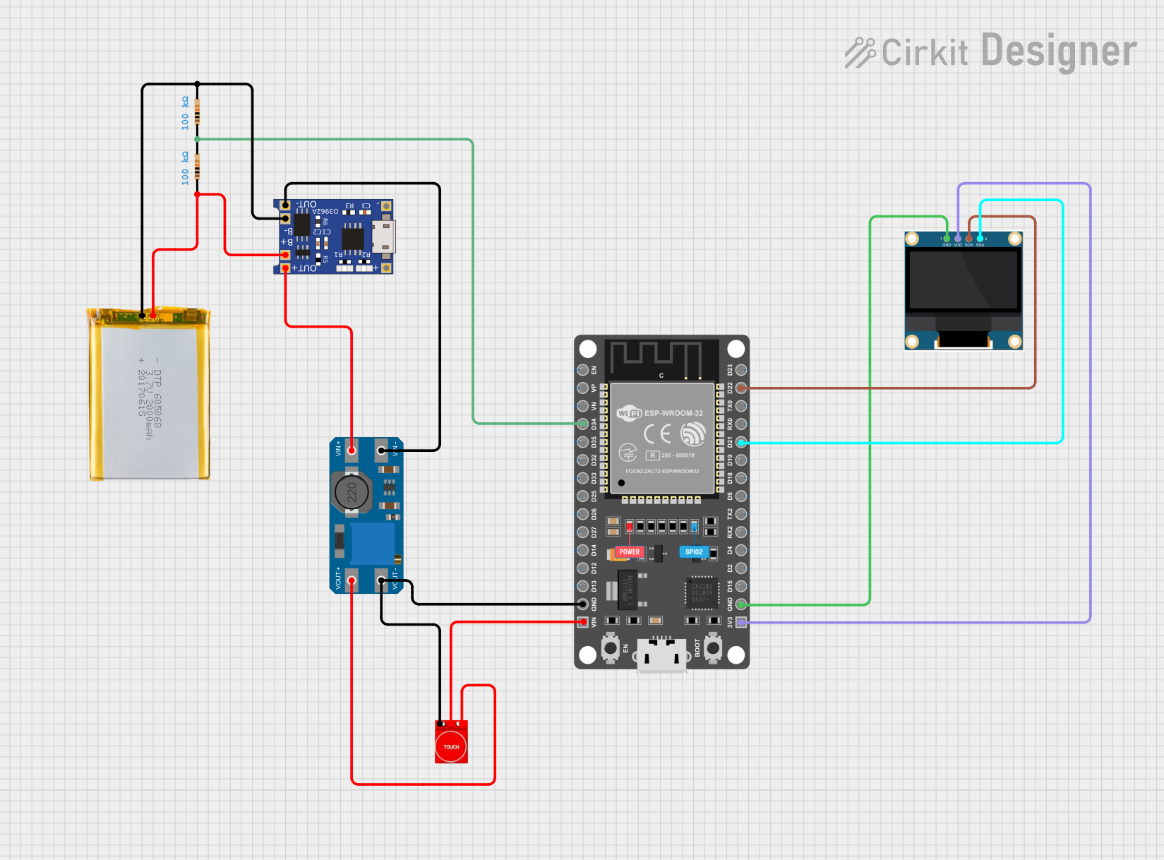
This circuit is designed to read the battery voltage connected to pin D34 of an ESP32 microcontroller and display the value on a 0.96" OLED display connected via I2C. The circuit also includes a battery indicator. The power is supplied by a 2000mAh battery, and the voltage is regulated using a TP4056 and MT3608 modules. A touch sensor is also included in the circuit.
Component List
Resistor
- Description: 100k Ohm resistor
- Pins: pin1, pin2
- Properties: Resistance: 100k Ohms
2000mAh Battery
- Description: Rechargeable battery
- Pins: VCC, GND
TP4056
- Description: Lithium battery charger module
- Pins: OUT-, B-, B+, OUT+, IN-, IN+
MT3608
- Description: DC-DC step-up converter
- Pins: VOUT+, VIN+, VOUT-, VIN-
Touch Sensor TTP233
- Description: Capacitive touch sensor
- Pins: GND, I/O, VCC
ESP 32 DEVKIT V1 (30 pins)
- Description: Microcontroller with WiFi and Bluetooth
- Pins: EN, VP, VN, D34, D35, D32, D33, D25, D26, D27, D14, D12, D13, GND, VIN, 3V3, D15, D2, D4, RX2, TX2, D5, D18, D19, D21, RX0, TX0, D22, D23
0.96" OLED
- Description: OLED display module
- Pins: GND, VDD, SCK, SDA
Wiring Details
Resistor 1
- Pin1 is connected to Pin2 of Resistor 2 and D34 of ESP32.
- Pin2 is connected to GND of the 2000mAh Battery and B- of TP4056.
Resistor 2
- Pin1 is connected to VCC of the 2000mAh Battery and B+ of TP4056.
- Pin2 is connected to Pin1 of Resistor 1 and D34 of ESP32.
2000mAh Battery
- VCC is connected to Pin1 of Resistor 2 and B+ of TP4056.
- GND is connected to Pin2 of Resistor 1 and B- of TP4056.
TP4056
- B+ is connected to VCC of the 2000mAh Battery and Pin1 of Resistor 2.
- B- is connected to GND of the 2000mAh Battery and Pin2 of Resistor 1.
- OUT+ is connected to VIN+ of MT3608.
- OUT- is connected to VIN- of MT3608.
MT3608
- VIN+ is connected to OUT+ of TP4056.
- VIN- is connected to OUT- of TP4056.
- VOUT+ is connected to VCC of Touch Sensor TTP233.
- VOUT- is connected to GND of Touch Sensor TTP233 and GND of ESP32.
Touch Sensor TTP233
- GND is connected to VOUT- of MT3608 and GND of ESP32.
- I/O is connected to VIN of ESP32.
- VCC is connected to VOUT+ of MT3608.
ESP 32 DEVKIT V1 (30 pins)
- D34 is connected to Pin1 of Resistor 1 and Pin2 of Resistor 2.
- GND is connected to VOUT- of MT3608 and GND of Touch Sensor TTP233.
- VIN is connected to I/O of Touch Sensor TTP233.
- 3V3 is connected to VDD of 0.96" OLED.
- D21 is connected to SDA of 0.96" OLED.
- D22 is connected to SCK of 0.96" OLED.
0.96" OLED
- VDD is connected to 3V3 of ESP32.
- GND is connected to GND of ESP32.
- SDA is connected to D21 of ESP32.
- SCK is connected to D22 of ESP32.
Code Documentation
/*
 * This Arduino Sketch reads the battery voltage connected to pin D34 of the ESP32
 * and displays the value on a 0.96" OLED display connected via I2C (SCK: D22, SDA: D21).
 * It also includes a battery indicator.
 */

#include <Wire.h>
#include <Adafruit_GFX.h>
#include <Adafruit_SSD1306.h>

#define SCREEN_WIDTH 128
#define SCREEN_HEIGHT 64
#define OLED_RESET -1
Adafruit_SSD1306 display(SCREEN_WIDTH, SCREEN_HEIGHT, &Wire, OLED_RESET);

void setup() {
  // Initialize serial communication at 115200 baud rate
  Serial.begin(115200);
  // Initialize the OLED display
  if(!display.begin(SSD1306_SWITCHCAPVCC, 0x3C)) {
    Serial.println(F("SSD1306 allocation failed"));
    for(;;);
  }
  display.display();
  delay(2000);
  display.clearDisplay();
}

void loop() {
  // Read the analog value from pin D34
  int analogValue = analogRead(34);
  // Convert the analog value to voltage (assuming 3.3V reference)
  float voltage = analogValue * (3.3 / 4095.0);
  // Print the voltage to the serial monitor
  Serial.print("Battery Voltage: ");
  Serial.print(voltage);
  Serial.println(" V");
  // Display the voltage on the OLED
  display.clearDisplay();
  display.setTextSize(1);
  display.setTextColor(SSD1306_WHITE);
  display.setCursor(0, 10);
  display.print("Battery Voltage: ");
  display.print(voltage);
  display.println(" V");
  // Draw battery indicator
  int batteryLevel = map(voltage, 3.0, 4.2, 0, 100);
  display.drawRect(0, 30, 100, 10, SSD1306_WHITE);
  display.fillRect(0, 30, batteryLevel, 10, SSD1306_WHITE);
  display.display();
  // Wait for a second before the next reading
  delay(1000);
}
This code initializes the OLED display and reads the battery voltage from pin D34 of the ESP32. The voltage is then displayed on the OLED along with a battery level indicator. The voltage is also printed to the serial monitor for debugging purposes.