Arduino UNO Based Ultrasonic Distance Measurement with LED and Buzzer Indicators
Circuit Documentation
Summary of the Circuit
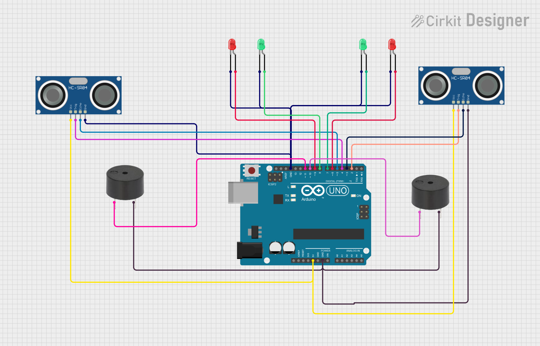
This circuit is designed around an Arduino UNO microcontroller and includes various peripherals such as two HC-SR04 ultrasonic sensors, multiple LEDs (both red and green), and two buzzers. The circuit is likely intended for distance measurement with audible and visual indicators. The Arduino UNO provides power to the sensors and controls the LEDs and buzzers based on the sensor inputs. However, no embedded code is provided, indicating that the functionality is not yet implemented or is not available.
Component List
Arduino UNO
- Microcontroller board based on the ATmega328P
- Provides I/O pins for interfacing with various components
- Supplies power to connected components
LED: Two Pin (red)
- Visual indicator
- Has an anode and cathode for connection
LED: Two Pin (green)
- Visual indicator
- Has an anode and cathode for connection
HC-SR04 Ultrasonic Sensor
- Used for distance measurement
- Has VCC, TRIG, ECHO, and GND pins
Buzzer
- Audible indicator
- Has a signal PIN and a GND connection
Wiring Details
Arduino UNO
- 5V pin provides power to both HC-SR04 ultrasonic sensors
- GND pin is connected to the ground pins of all components
- Digital pins D2 to D11 are used to interface with the ultrasonic sensors, buzzers, and LEDs
LED: Two Pin (red)
- Cathode connected to GND
- Anode connected to Arduino digital pins D6 and D9
LED: Two Pin (green)
- Cathode connected to GND
- Anode connected to Arduino digital pins D7 and D8
HC-SR04 Ultrasonic Sensor
- VCC connected to 5V from the Arduino
- GND connected to GND on the Arduino
- TRIG connected to Arduino digital pins D2 and D4
- ECHO connected to Arduino digital pins D3 and D5
Buzzer
- GND connected to GND on the Arduino
- PIN connected to Arduino digital pins D10 and D11
Documented Code
No code has been provided for the microcontroller. The expected functionality would include initializing the I/O pins, reading distance measurements from the HC-SR04 sensors, and then activating the LEDs and buzzers based on predefined distance thresholds. Without the code, the specific behavior of the circuit cannot be documented.