
Arduino and ESP8266 Nodemcu Based Smart Water Level Monitoring System
View and Edit Project In Cirkit Designer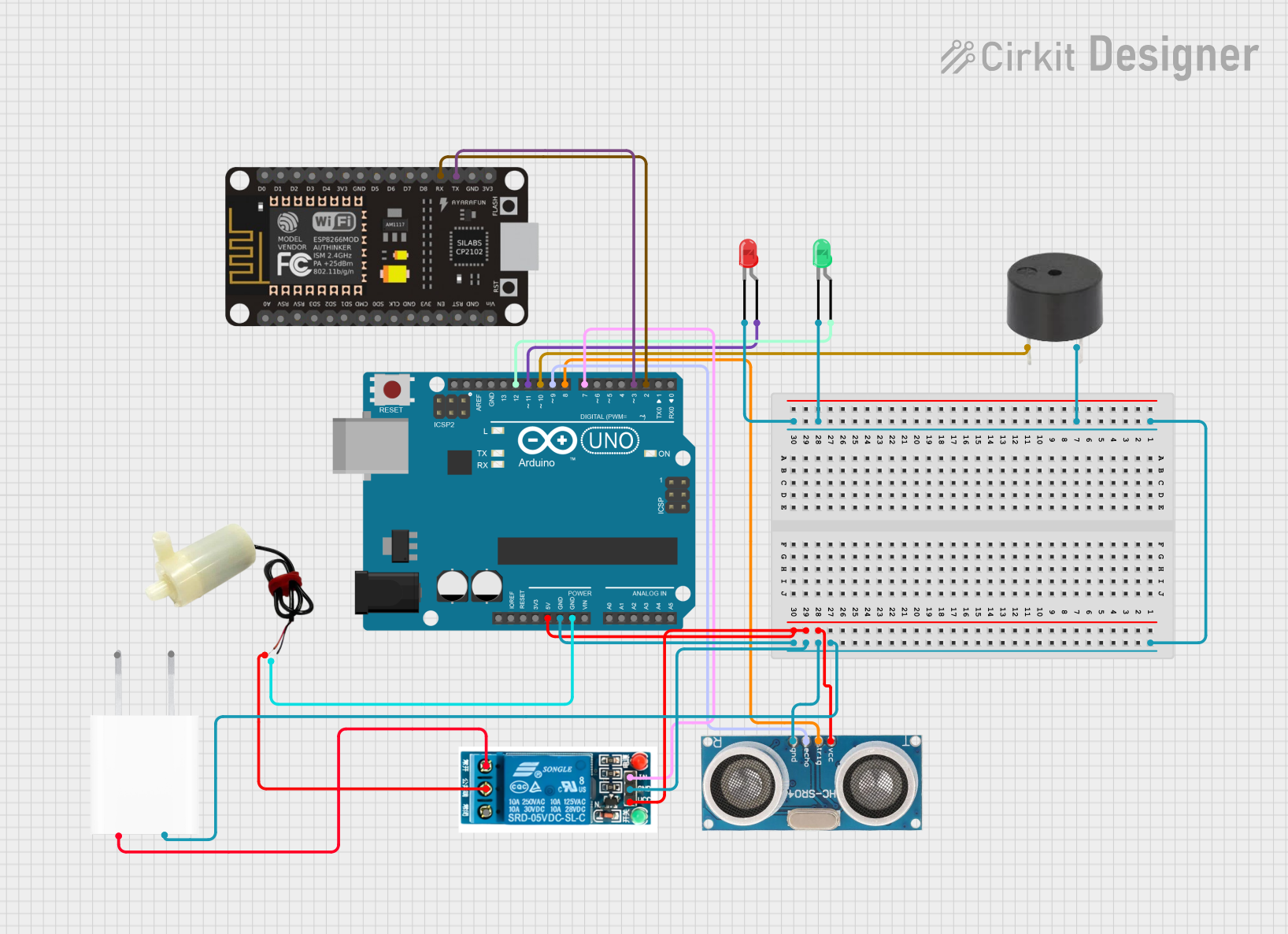
Circuit Documentation
Summary
This circuit is designed to monitor water levels using an ultrasonic sensor and control a water pump accordingly. It features visual indicators (LEDs) and an audible alert (buzzer) to signal water level status. The system is controlled by an Arduino UNO microcontroller, which communicates with an ESP8266 NodeMCU for potential IoT capabilities. A 5V relay is used to switch the water pump on and off, and a 5V adapter provides power to the circuit.
Component List
Buzzer
- Description: An audible alert device that generates sound when powered.
- Pins: PIN, GND
5V Adapter
- Description: A power supply that converts AC to a 5V DC output.
- Pins: AC In 1, AC In 2, 5V, GND
5V Relay
- Description: An electromechanical switch that allows a low-power circuit to control a high-power circuit.
- Pins: Normally Open, Common terminal, Normally Closed, In, GND, VCC
ESP8266 NodeMCU
- Description: A Wi-Fi enabled microcontroller for IoT applications.
- Pins: D0-D8, RX, TX, A0, RSV, SD3, SD2, SD1, CMD, SD0, CLK, EN, RST, VIN, 3V3, GND
LED: Two Pin (Green)
- Description: A green light-emitting diode used as a visual indicator.
- Pins: Cathode, Anode
LED: Two Pin (Red)
- Description: A red light-emitting diode used as a visual indicator.
- Pins: Cathode, Anode
5V Mini Water Pump
- Description: A small pump that operates on 5V for moving water.
- Pins: Positive pin, Negative pin
Ultrasonic Sensor
- Description: A sensor that measures distance using ultrasonic waves.
- Pins: +VCC, Trigger, Echo, GND
Arduino UNO
- Description: A microcontroller board based on the ATmega328P.
- Pins: UNUSED, IOREF, Reset, 3.3V, 5V, GND, Vin, A0-A5, SCL, SDA, AREF, D0-D13
Wiring Details
Buzzer
- PIN connected to Arduino UNO D10
- GND connected to common ground
5V Adapter
- 5V connected to 5V relay Normally Open
- GND connected to common ground
5V Relay
- Common terminal connected to 5V mini water pump positive pin
- In connected to Arduino UNO D7
- GND connected to common ground
- VCC connected to Arduino UNO 5V
ESP8266 NodeMCU
- TX connected to Arduino UNO D3
- RX connected to Arduino UNO D2
- GND connected to common ground (not explicitly mentioned, but assumed for proper operation)
LED: Two Pin (Green)
- Cathode connected to common ground
- Anode connected to Arduino UNO D12
LED: Two Pin (Red)
- Cathode connected to common ground
- Anode connected to Arduino UNO D11
5V Mini Water Pump
- Positive pin connected to 5V relay Common terminal
- Negative pin connected to common ground
Ultrasonic Sensor
- +VCC connected to Arduino UNO 5V
- Trigger connected to Arduino UNO D8
- Echo connected to Arduino UNO D9
- GND connected to common ground
Arduino UNO
- 5V connected to Ultrasonic Sensor +VCC and 5V relay VCC
- GND connected to common ground
- D8 connected to Ultrasonic Sensor Trigger
- D9 connected to Ultrasonic Sensor Echo
- D10 connected to Buzzer PIN
- D11 connected to LED: Two Pin (Red) Anode
- D12 connected to LED: Two Pin (Green) Anode
- D7 connected to 5V relay In
- D3 connected to ESP8266 NodeMCU TX
- D2 connected to ESP8266 NodeMCU RX
Documented Code
Arduino UNO Code (sketch.ino)
void setup() {
  pinMode(8, OUTPUT); // Trigger pin
  pinMode(9, INPUT);  // Echo pin
  pinMode(10, OUTPUT); // Buzzer
  pinMode(11, OUTPUT); // Red LED
  pinMode(12, OUTPUT); // Green LED
  pinMode(7, OUTPUT);  // Relay control
  Serial.begin(9600);  // Communication with ESP8266
}

void loop() {
  // Measure water level
  long duration, distance;
  digitalWrite(8, LOW);
  delayMicroseconds(2);
  digitalWrite(8, HIGH);
  delayMicroseconds(10);
  digitalWrite(8, LOW);
  duration = pulseIn(9, HIGH);
  distance = (duration / 2) / 29.1;

  if (distance < 10) { // Water level low
    digitalWrite(11, HIGH); // Red LED on
    digitalWrite(10, HIGH); // Buzzer on
    digitalWrite(7, HIGH);  // Turn on water pump
    Serial.println("LOW WATER LEVEL");
  } else if (distance > 30) { // Water level full
    digitalWrite(12, HIGH); // Green LED on
    digitalWrite(10, HIGH); // Buzzer on
    digitalWrite(7, LOW);   // Turn off water pump
    Serial.println("FULL WATER LEVEL");
  } else {
    digitalWrite(11, LOW); // Red LED off
    digitalWrite(12, LOW); // Green LED off
    digitalWrite(10, LOW); // Buzzer off
  }

  delay(1000); // Wait for a second before next measurement
}
This code configures the Arduino UNO pins for input and output to interface with the ultrasonic sensor, LEDs, buzzer, and relay. It contains a loop that measures the water level and activates the appropriate indicators and controls the water pump based on the measured distance. Serial communication is established for potential data transmission to the ESP8266 NodeMCU.