
Arduino-Controlled Servo and DC Motor with NRF24L01 Wireless Communication
View and Edit Project In Cirkit Designer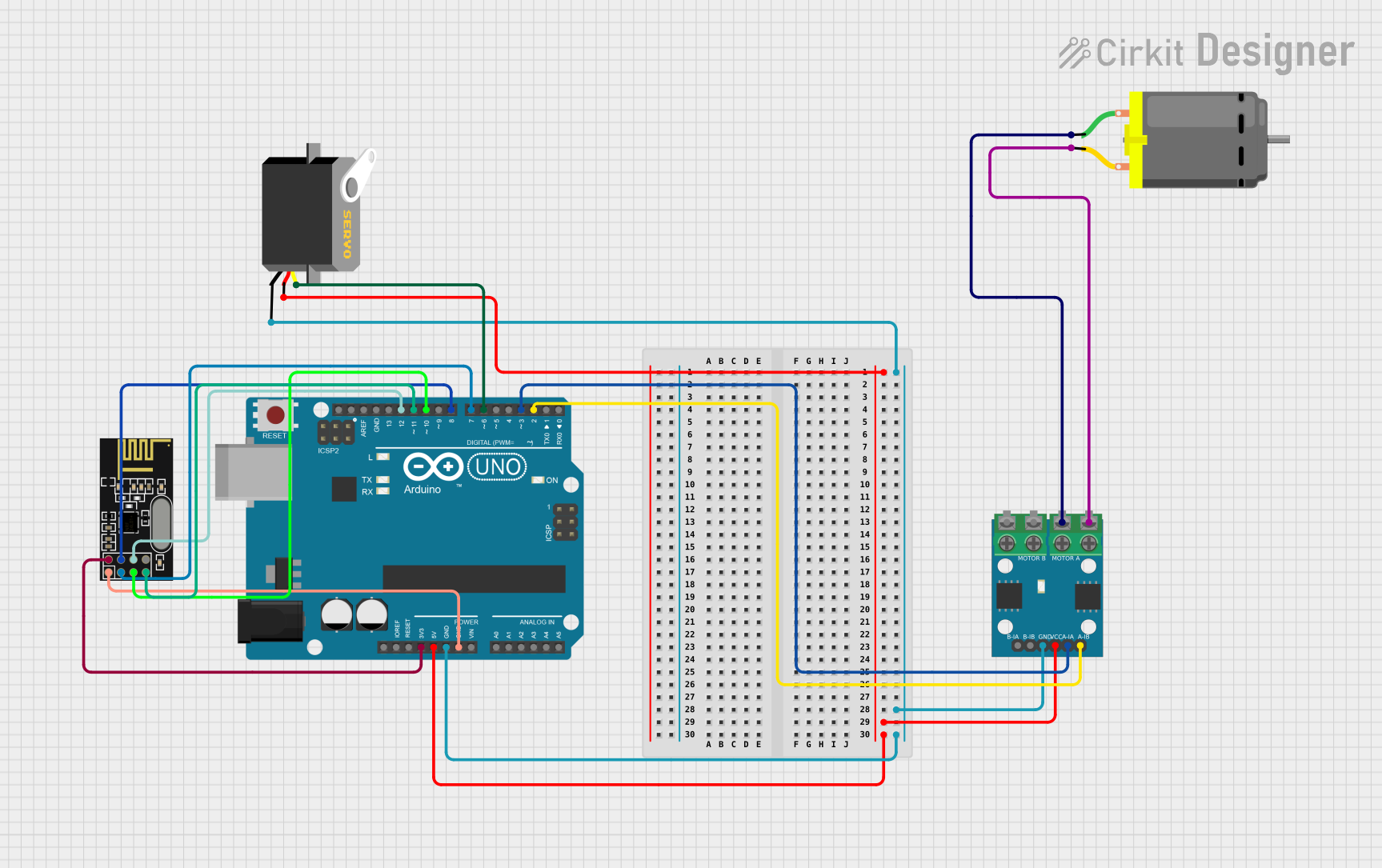
Circuit Documentation
Summary of the Circuit
This circuit is designed to control a DC motor and a servo motor using an Arduino UNO microcontroller. It also includes an L9110 motor driver to drive the DC motor and an NRF24L01 module for potential wireless communication. The Arduino UNO is the central processing unit that interfaces with the L9110 motor driver to control the DC motor's speed and direction, and it directly controls the servo motor's position. The NRF24L01 module is connected to the Arduino for possible wireless communication, although its specific use is not defined in the provided code.
Component List
L9110 Motor Driver
- Description: A dual-channel motor driver capable of driving a small DC motor.
- Pins: MOTOR B-A, MOTOR B-B, MOTOR A-A, MOTOR A-B, B-IA, B-IB, GND, VCC, A-IA, A-IB
DC Motor
- Description: A standard DC motor used for various mechanical movements.
- Pins: pin 1, pin 2
Arduino UNO
- Description: A microcontroller board based on the ATmega328P, widely used for prototyping and educational purposes.
- Pins: UNUSED, IOREF, Reset, 3.3V, 5V, GND, Vin, A0, A1, A2, A3, A4, A5, SCL, SDA, AREF, D13, D12, D11, D10, D9, D8, D7, D6, D5, D4, D3, D2, D1, D0
Servo Motor
- Description: A rotary actuator or linear actuator that allows for precise control of angular or linear position.
- Pins: gnd, vcc, pulse
NRF24L01 Module
- Description: A wireless transceiver module that operates in the 2.4 GHz band.
- Pins: IRQ (not used), MOSI, CSN, VCC (3V), GND, CE, SCK, MISO
Wiring Details
L9110 Motor Driver
- VCC connected to Arduino UNO 5V
- GND connected to Arduino UNO GND
- A-IA connected to Arduino UNO D3
- A-IB connected to Arduino UNO D2
- MOTOR A-A connected to DC Motor pin 2
- MOTOR A-B connected to DC Motor pin 1
DC Motor
- pin 1 connected to L9110 MOTOR A-B
- pin 2 connected to L9110 MOTOR A-A
Arduino UNO
- 5V connected to L9110 VCC and Servo vcc
- GND connected to L9110 GND, Servo gnd, and NRF24L01 GND
- 3.3V connected to NRF24L01 VCC (3V)
- D12 connected to NRF24L01 MOSI
- D11 connected to NRF24L01 MISO
- D10 connected to NRF24L01 SCK
- D8 connected to NRF24L01 CSN
- D7 connected to NRF24L01 CE
- D6 connected to Servo pulse
- D3 connected to L9110 A-IA
- D2 connected to L9110 A-IB
Servo Motor
- vcc connected to Arduino UNO 5V
- gnd connected to Arduino UNO GND
- pulse connected to Arduino UNO D6
NRF24L01 Module
- VCC (3V) connected to Arduino UNO 3.3V
- GND connected to Arduino UNO GND
- MOSI connected to Arduino UNO D12
- MISO connected to Arduino UNO D11
- SCK connected to Arduino UNO D10
- CSN connected to Arduino UNO D8
- CE connected to Arduino UNO D7
Documented Code
Arduino UNO Code (sketch.ino)
void setup() {
  // put your setup code here, to run once:

}

void loop() {
  // put your main code here, to run repeatedly:

}
Note: The provided code is a template and does not include specific functionality. It needs to be completed with the logic to control the DC motor, servo motor, and NRF24L01 module.