
Circuit Documentation
Summary
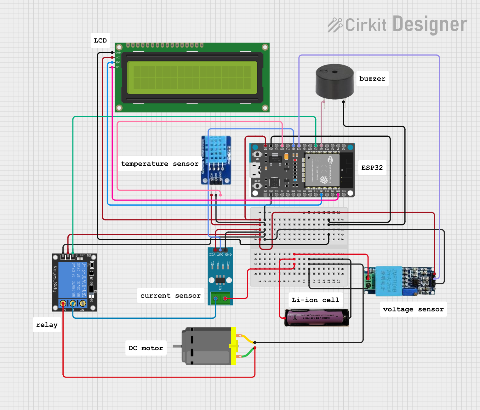
The circuit in question is designed to monitor and control various parameters such as current, voltage, temperature, and humidity. It includes an ESP32 Devkit V1 microcontroller as the central processing unit, interfaced with a range of sensors and output devices including an ACS712 current sensor, a voltage sensor, a DHT11 temperature and humidity sensor, a buzzer, an I2C LCD display, a relay module, and a DC motor. The ESP32 Devkit V1 is responsible for reading sensor data, displaying information on the LCD, and controlling the relay and buzzer based on specific conditions.
Component List
ESP32 Devkit V1
- Microcontroller with WiFi capability
- Pins: 3V3, GND, D15, D2, D4, RX2, TX2, D5, D18, D19, D21, RX0, TX0, D22, D23, EN, VP, VN, D34, D35, D32, D33, D25, D26, D27, D14, D12, D13, VIN
ACS712 Current Sensor (5A, 20A, 30A)
- Hall-effect-based linear current sensor
- Pins: 1, 2, GND, OUT, VCC
Voltage Sensor
- Module for measuring voltage in a circuit
- Pins: Ground, Phase, Vcc, Out, Gnd
3.7V Battery
- Power source for the circuit
- Pins: +, -
DHT11
- Temperature and humidity sensor
- Pins: DATA, GND, VCC
Buzzer
- Audio signaling device
- Pins: PIN, GND
16x2 I2C LCD
- Alphanumeric Liquid Crystal Display with I2C interface
- Pins: GND, VCC, SDA, SCL
1-Channel Relay (5V, 10A)
- Electromechanical switch used for controlling high power devices
- Pins: NC, signal, C, power, NO, ground
DC Motor
- Electric motor that runs on direct current electricity
- Pins: pin 1, pin 2
Wiring Details
ESP32 Devkit V1
- GND connected to the ground of the relay, ACS712, DHT11, voltage sensor, buzzer, and LCD
- D21 (SDA) connected to the SDA pin of the LCD
- D22 (SCL) connected to the SCL pin of the LCD
- D35 connected to the buzzer PIN
- D32 connected to the relay signal pin
- D26 connected to the voltage sensor Out pin
- D27 connected to the ACS712 OUT pin
- D12 connected to the DHT11 DATA pin
- VIN connected to the power pin of the relay, VCC of the LCD, ACS712, DHT11, and voltage sensor
ACS712 Current Sensor
- GND connected to the ground of the circuit
- OUT connected to the ESP32 Devkit V1 D27
- VCC connected to the ESP32 Devkit V1 VIN
- 1 connected to the relay C pin
- 2 connected to the positive pin of the 3.7V battery
Voltage Sensor
- Ground connected to the negative pin of the 3.7V battery
- Phase connected to the pin 2 of the DC motor
- Vcc connected to the ESP32 Devkit V1 VIN
- Out connected to the ESP32 Devkit V1 D26
- Gnd connected to the ground of the circuit
3.7V Battery
-
- connected to the ACS712 pin 2
-
- connected to the ground of the voltage sensor and pin 2 of the DC motor
DHT11
- DATA connected to the ESP32 Devkit V1 D12
- GND connected to the ground of the circuit
- VCC connected to the ESP32 Devkit V1 VIN
Buzzer
- PIN connected to the ESP32 Devkit V1 D35
- GND connected to the ground of the circuit
16x2 I2C LCD
- GND connected to the ground of the circuit
- VCC connected to the ESP32 Devkit V1 VIN
- SDA connected to the ESP32 Devkit V1 D21
- SCL connected to the ESP32 Devkit V1 D22
1-Channel Relay
- ground connected to the ground of the circuit
- signal connected to the ESP32 Devkit V1 D32
- C connected to the ACS712 pin 1
- power connected to the ESP32 Devkit V1 VIN
- NO connected to the pin 1 of the DC motor
DC Motor
- pin 1 connected to the NO pin of the relay
- pin 2 connected to the negative pin of the 3.7V battery and the Phase pin of the voltage sensor
Documented Code
No code was provided for the microcontroller. The documentation of the code would typically include a description of the functionality, setup, and loop sections, along with comments explaining the purpose of each function and variable. Since no code is available, this section cannot be completed.