
Circuit Documentation
Summary of the Circuit
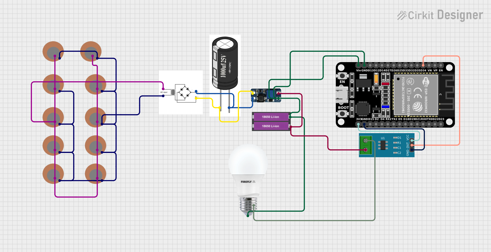
The circuit in question appears to be a power harvesting system using multiple piezoelectric sensors connected in parallel to a bridge rectifier. The rectified output is then smoothed by a capacitor and boosted by a DC-DC converter to power an ESP32 microcontroller and a bulb. The ESP32 monitors the current flow to the bulb using a current sensor. The system is powered by two 18650 Li-ion batteries connected in series.
Component List
Piezo Sensor
- Description: A sensor that generates electrical charge in response to mechanical stress.
- Purpose: Used for harvesting energy from mechanical vibrations or impacts.
- Pins:
+,-
Bridge Rectifier
- Description: A component that converts alternating current (AC) to direct current (DC).
- Purpose: Rectifies the AC voltage generated by the piezo sensors.
- Pins:
AC input +,AC input -,+,-
1000uf/25V Capacitor
- Description: An electrolytic capacitor with a capacitance of 1000 microfarads and a voltage rating of 25 volts.
- Purpose: Smoothes out the rectified voltage from the bridge rectifier.
- Pins:
+,-
DC-DC BOOST CONVERTOR
- Description: A power supply module that steps up the input voltage to a higher output voltage.
- Purpose: Boosts the voltage to a level suitable for powering the ESP32 and the bulb.
- Pins:
VIN-,VIN+,VOUT+,VOUT-
18650 Li-ion Battery x 2
- Description: Rechargeable lithium-ion batteries commonly used in high-drain applications.
- Purpose: Provides the primary power source for the circuit.
- Pins:
+,-
ESP32 (30 pin)
- Description: A microcontroller with Wi-Fi and Bluetooth capabilities.
- Purpose: Controls the circuit operation and processes sensor data.
- Pins:
EN,VP,VN,D34,D35,D32,D33,D25,D26,D27,D14,D12,D13,GND,Vin,D23,D22,TX0,RX0,D21,D19,D18,D5,TX2,RX2,D4,D2,D15,3V3
Current Sensor 5A
- Description: A sensor for measuring electrical current up to 5 amperes.
- Purpose: Measures the current supplied to the bulb.
- Pins:
1,2,GND,OUT,VCC
BULB
- Description: An electric light source.
- Purpose: Acts as a load in the circuit and is powered by the harvested energy.
- Pins:
+,-
Wiring Details
Piezo Sensors
- Positive Pin (
+): Connected in parallel to theAC input +of the Bridge Rectifier. - Negative Pin (
-): Connected in parallel to theAC input -of the Bridge Rectifier.
Bridge Rectifier
- AC Input Pins (
AC input +,AC input -): Connected to the positive and negative pins of the Piezo Sensors, respectively. - Positive Output Pin (
+): Connected to theVIN+of the DC-DC BOOST CONVERTOR and the positive pin of the 1000uf/25V capacitor. - Negative Output Pin (
-): Connected to theVIN-of the DC-DC BOOST CONVERTOR and the negative pin of the 1000uf/25V capacitor.
1000uf/25V Capacitor
- Positive Pin (
+): Connected to the positive output of the Bridge Rectifier. - Negative Pin (
-): Connected to the negative output of the Bridge Rectifier.
DC-DC BOOST CONVERTOR
- Input Pins (
VIN-,VIN+): Connected to the corresponding negative and positive outputs of the Bridge Rectifier. - Output Pins (
VOUT+,VOUT-):VOUT+is connected to theVinof the ESP32, the positive pin of the bulb, and the positive terminal of the 18650 Li-ion Battery.VOUT-is connected to the negative terminal of the 18650 Li-ion Battery and pin2of the Current Sensor 5A.
18650 Li-ion Battery x 2
- Positive Terminal (
+): Connected to theVOUT+of the DC-DC BOOST CONVERTOR and the positive pin of the bulb. - Negative Terminal (
-): Connected to theVOUT-of the DC-DC BOOST CONVERTOR and pin1of the Current Sensor 5A.
ESP32 (30 pin)
- Ground Pin (
GND): Connected to the ground of the circuit. - Voltage Input Pin (
Vin): Connected to theVOUT+of the DC-DC BOOST CONVERTOR. - Digital Pin (
D34): Connected to theOUTpin of the Current Sensor 5A. - 3.3V Pin (
3V3): Connected to theVCCpin of the Current Sensor 5A.
Current Sensor 5A
- Pin
1: Connected to the negative pin of the bulb. - Pin
2: Connected to theVOUT-of the DC-DC BOOST CONVERTOR. - Ground Pin (
GND): Connected to the ground of the circuit. - Output Pin (
OUT): Connected to theD34pin of the ESP32. - Voltage Supply Pin (
VCC): Connected to the3V3pin of the ESP32.
BULB
- Positive Pin (
+): Connected to theVOUT+of the DC-DC BOOST CONVERTOR and the positive terminal of the 18650 Li-ion Battery. - Negative Pin (
-): Connected to pin1of the Current Sensor 5A.
Documented Code
There is no code provided for the microcontroller in this circuit. If code is later provided, it should be documented here with explanations of its functionality and how it interacts with the hardware components of the circuit.