Arduino UNO Controlled Dual LED Blinker
Circuit Documentation
Summary of the Circuit
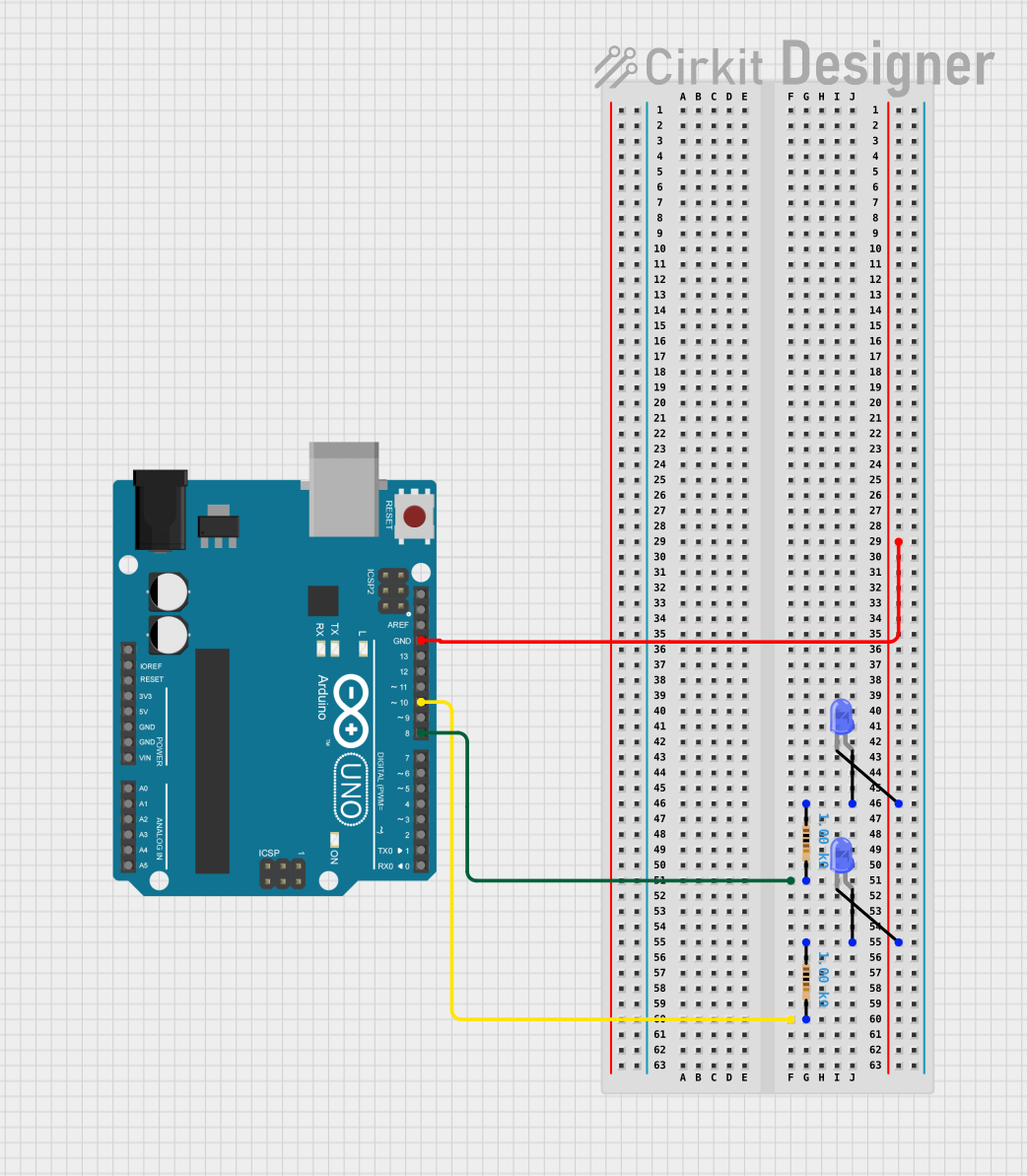
This circuit consists of an Arduino UNO microcontroller that is used to control two blue LEDs. Each LED is connected in series with a 1k Ohm resistor. The purpose of the resistors is to limit the current flowing through the LEDs to prevent damage. The LEDs are connected to digital pins D8 and D10 on the Arduino UNO, and their cathodes are connected to the ground (GND) pin of the Arduino UNO.
Component List
Arduino UNO
- Description: A microcontroller board based on the ATmega328P.
- Pins: UNUSED, IOREF, Reset, 3.3V, 5V, GND, Vin, A0-A5, SCL, SDA, AREF, D0-D13.
LED: Two Pin (blue)
- Description: A standard blue light-emitting diode.
- Pins: Anode, Cathode.
Resistor
- Description: A passive two-terminal electrical component that implements electrical resistance as a circuit element.
- Value: 1000 Ohms (1k Ohm).
- Pins: Pin1, Pin2.
Wiring Details
Arduino UNO
- Digital Pin D8: Connected to one end of a 1k Ohm resistor.
- Digital Pin D10: Connected to one end of another 1k Ohm resistor.
- GND: Connected to the cathodes of both blue LEDs.
LED: Two Pin (blue) #1
- Anode: Connected to one end of a 1k Ohm resistor.
- Cathode: Connected to the GND pin on the Arduino UNO.
LED: Two Pin (blue) #2
- Anode: Connected to one end of another 1k Ohm resistor.
- Cathode: Connected to the GND pin on the Arduino UNO.
Resistor #1
- Pin1: Connected to the anode of the first blue LED.
- Pin2: Connected to Digital Pin D8 on the Arduino UNO.
Resistor #2
- Pin1: Connected to the anode of the second blue LED.
- Pin2: Connected to Digital Pin D10 on the Arduino UNO.
Documented Code
The code for the Arduino UNO is provided in a file named sketch.ino. The code is currently a template with empty setup() and loop() functions, which are placeholders for initialization code and the main logic that will run repeatedly, respectively.
void setup() {
  // put your setup code here, to run once:

}

void loop() {
  // put your main code here, to run repeatedly:

}
Additional documentation or code can be provided in a text file named documentation.txt. Currently, this file does not contain any content.