
ESP32-CAM Wi-Fi Controlled Robotic Car with Camera and Motor Driver
View and Edit Project In Cirkit Designer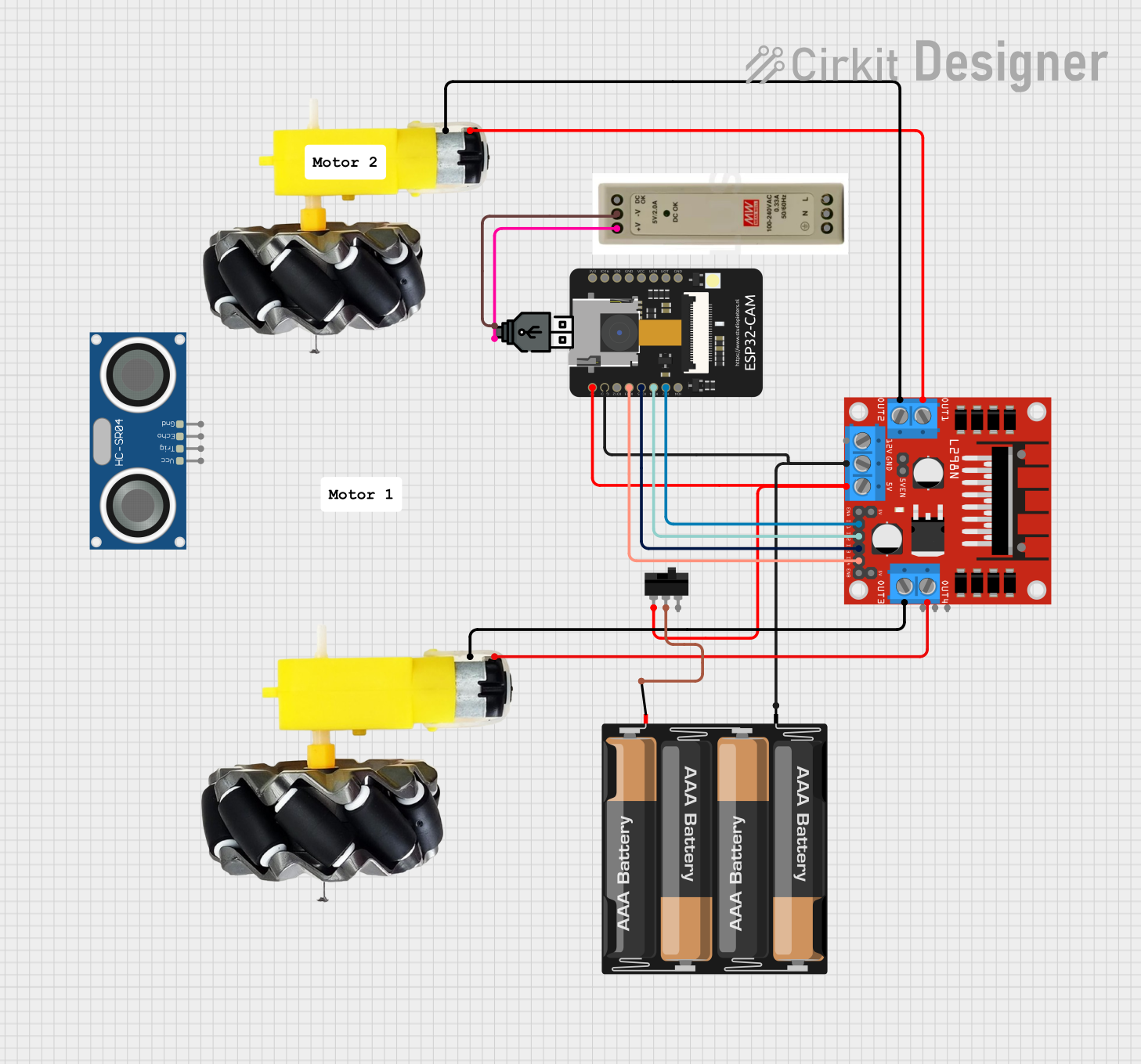
Circuit Documentation
Summary
This document provides a detailed overview of a circuit designed to control a car using an ESP32-CAM microcontroller. The circuit includes motor drivers, motors, a toggle switch, a power supply, and an ultrasonic sensor. The ESP32-CAM is programmed to control the motors and capture images, while also providing a web interface for remote control.
Component List
Motor and Wheels
- Description: Motor and wheel assembly for driving the car.
- Pins: vcc, GND
ESP32-CAM
- Description: Microcontroller with camera and WiFi capabilities.
- Pins: 5V, GND, IO12, IO13, IO15, IO14, IO2, IO4, VOT, VOR, VCC, IO0, IO16, 3V3
Toggle Switch
- Description: Switch to control power to the circuit.
- Pins: L1, COM, L2
USB Power
- Description: USB power supply.
- Pins: +, -
5V PSU
- Description: 5V power supply unit.
- Pins: 5V+, GND, 5V OK, PE, N, L
HC-SR04 Ultrasonic Sensor
- Description: Ultrasonic sensor for distance measurement.
- Pins: VCC, TRIG, ECHO, GND
L298N DC Motor Driver
- Description: Motor driver for controlling DC motors.
- Pins: OUT1, OUT2, 12V, GND, 5V, OUT3, OUT4, 5V-ENA-JMP-I, 5V-ENA-JMP-O, +5V-J1, +5V-J2, ENA, IN1, IN2, IN3, IN4, ENB
4 x AAA Battery Mount
- Description: Battery holder for 4 AAA batteries.
- Pins: -, +
Wiring Details
Motor and Wheels
Motor 1:
- vcc connected to OUT1 of L298N DC Motor Driver
- GND connected to OUT2 of L298N DC Motor Driver
Motor 2:
- vcc connected to OUT4 of L298N DC Motor Driver
- GND connected to OUT3 of L298N DC Motor Driver
ESP32-CAM
- 5V connected to 5V of L298N DC Motor Driver and L1 of Toggle Switch
- GND connected to - of 4 x AAA Battery Mount and GND of L298N DC Motor Driver
- IO13 connected to IN4 of L298N DC Motor Driver
- IO15 connected to IN3 of L298N DC Motor Driver
- IO14 connected to IN2 of L298N DC Motor Driver
- IO2 connected to IN1 of L298N DC Motor Driver
Toggle Switch
- COM connected to + of 4 x AAA Battery Mount
USB Power
- + connected to 5V+ of 5V PSU
- - connected to GND of 5V PSU
5V PSU
- 5V+ connected to + of USB Power
- GND connected to - of USB Power
Code Documentation
ESP32-CAM Code
/*
 * ESP32-CAM Car Control with Camera and WiFi
 * This code controls the L298N motor driver to drive the motors
 * connected to the car. The ESP32-CAM uses its GPIO pins to control
 * the direction and speed of the motors. Additionally, it initializes
 * the camera for capturing images and connects to a WiFi network.
 * It also sets up a web server with HTML buttons for controlling the car.
 */

#include "esp_camera.h"
#include <WiFi.h>
#include <WebServer.h>

//=====================
//Select camera model
//=====================
//#define CAMERA_MODEL_WROVER_KIT // Has PSRAM
//#define CAMERA_MODEL_ESP_EYE  // Has PSRAM
//#define CAMERA_MODEL_AI_THINKER // Has PSRAM

// Define motor control pins
#define IN1 2
#define IN2 14
#define IN3 15
#define IN4 13

// Camera configuration
#define PWDN_GPIO_NUM    -1
#define RESET_GPIO_NUM   -1
#define XCLK_GPIO_NUM    0
#define SIOD_GPIO_NUM    26
#define SIOC_GPIO_NUM    27
#define Y9_GPIO_NUM      35
#define Y8_GPIO_NUM      34
#define Y7_GPIO_NUM      39
#define Y6_GPIO_NUM      36
#define Y5_GPIO_NUM      21
#define Y4_GPIO_NUM      19
#define Y3_GPIO_NUM      18
#define Y2_GPIO_NUM      5
#define VSYNC_GPIO_NUM   25
#define HREF_GPIO_NUM    23
#define PCLK_GPIO_NUM    22

// WiFi credentials
const char* ssid = "your_SSID";
const char* password = "your_PASSWORD";

WebServer server(80);

void handleRoot() {
  String html = "<html><body>";
  html += "<h1>ESP32-CAM Car Control</h1>";
  html += "<button onclick=\"location.href='/forward'\">Forward</button>";
  html += "<button onclick=\"location.href='/backward'\">Backward</button>";
  html += "<button onclick=\"location.href='/left'\">Left</button>";
  html += "<button onclick=\"location.href='/right'\">Right</button>";
  html += "<button onclick=\"location.href='/stop'\">Stop</button>";
  html += "</body></html>";
  server.send(200, "text/html", html);
}

void handleForward() {
  digitalWrite(IN1, HIGH);
  digitalWrite(IN2, LOW);
  digitalWrite(IN3, HIGH);
  digitalWrite(IN4, LOW);
  server.send(200, "text/plain", "Moving forward");
}

void handleBackward() {
  digitalWrite(IN1, LOW);
  digitalWrite(IN2, HIGH);
  digitalWrite(IN3, LOW);
  digitalWrite(IN4, HIGH);
  server.send(200, "text/plain", "Moving backward");
}

void handleLeft() {
  digitalWrite(IN1, LOW);
  digitalWrite(IN2, HIGH);
  digitalWrite(IN3, HIGH);
  digitalWrite(IN4, LOW);
  server.send(200, "text/plain", "Turning left");
}

void handleRight() {
  digitalWrite(IN1, HIGH);
  digitalWrite(IN2, LOW);
  digitalWrite(IN3, LOW);
  digitalWrite(IN4, HIGH);
  server.send(200, "text/plain", "Turning right");
}

void handleStop() {
  digitalWrite(IN1, LOW);
  digitalWrite(IN2, LOW);
  digitalWrite(IN3, LOW);
  digitalWrite(IN4, LOW);
  server.send(200, "text/plain", "Stopped");
}

void setup() {
  Serial.begin(115200);

  // Initialize motor control pins as outputs
  pinMode(IN1, OUTPUT);
  pinMode(IN2, OUTPUT);
  pinMode(IN3, OUTPUT);
  pinMode(IN4, OUTPUT);

  // Initialize camera
  camera_config_t config;
  config.ledc_channel = LEDC_CHANNEL_0;
  config.ledc_timer = LEDC_TIMER_0;
  config.pin_d0 = Y2_GPIO_NUM;
  config.pin_d1 = Y3_GPIO_NUM;
  config.pin_d2 = Y4_GPIO_NUM;
  config.pin_d3 = Y5_GPIO_NUM;
  config.pin_d4 = Y6_GPIO_NUM;
  config.pin_d5 = Y7_GPIO_NUM;
  config.pin_d6 = Y8_GPIO_NUM;
  config.pin_d7 = Y9_GPIO_NUM;
  config.pin_xclk = XCLK_GPIO_NUM;
  config.pin_pclk = PCLK_GPIO_NUM;
  config.pin_vsync = VSYNC_GPIO_NUM;
  config.pin_href = HREF_GPIO_NUM;
  config.pin_sscb_sda = SIOD_GPIO_NUM;
  config.pin_sscb_scl = SIOC_GPIO_NUM;
  config.pin_pwdn = PWDN_GPIO_NUM;
  config.pin_reset = RESET_GPIO_NUM;
  config.xclk_freq_hz = 20000000;
  config.pixel_format = PIXFORMAT_JPEG;

  if(psramFound()){
    config.frame_size = FRAMESIZE_UXGA;
    config.jpeg_quality = 10;
    config.fb_count = 2;
  } else {
    config.frame_size = FRAMESIZE_SVGA;
    config.jpeg_quality = 12;
    config.fb_count = 1;
  }

  // Camera init
  esp_err_t err = esp_camera_init(&config);
  if (err != ESP_OK) {
    Serial.printf("Camera init failed with error 0x%x", err);
    return;
  }

  // Connect to WiFi
  WiFi.begin(ssid, password);