
ESP8266-Based Portable Communication Device with GPS Tracking and OLED/LCD Display
View and Edit Project In Cirkit Designer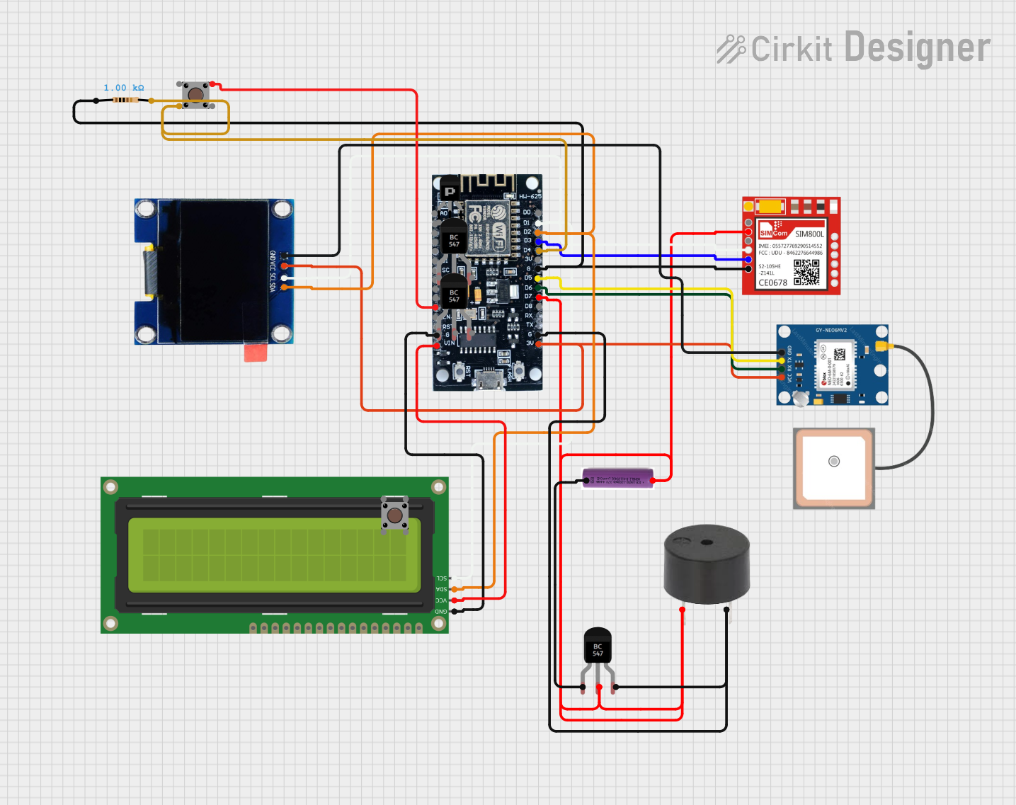
Circuit Documentation
Summary of the Circuit
This circuit integrates various components to create a multifunctional system. It includes an ESP8266 microcontroller, which serves as the central processing unit, interfacing with a SIM800L GSM module, a GPS NEO 6M module for location tracking, an OLED display, and a 16x2 I2C LCD for user interface. The circuit is powered by a 3.7V battery and includes a buzzer for audio feedback, multiple pushbuttons for user input, and transistors for controlling power to certain components. The ESP8266 manages the communication between the modules and displays relevant information to the user through the displays.
Component List
ESP8266
- Microcontroller with WiFi capability.
- Pins: 3V, G, D8, D7, D6, D5, D4, D3, D2, D1, D0, A0, S3, S2, S1, SC, S0, SK, EN, VIN, RST, VU.
Sim800l
- GSM/GPRS module for cellular communication.
- Pins: NET, RST, VCC, RXD, TXD, GND.
3.7V Battery
- Power source for the circuit.
- Pins: +, -.
GPS NEO 6M
- GPS module for location tracking.
- Pins: VCC, RX, TX, GND.
OLED 1.3"
- Small display for visual output.
- Pins: GND, VCC, SCL, SDA.
16x2 I2C LCD
- Alphanumeric display for visual output.
- Pins: GND, VCC, SDA, SCL.
Buzzer
- Audio output device.
- Pins: PIN, GND.
Resistor (1k Ohms)
- Used for current limiting and pull-up/pull-down configurations.
- Pins: pin1, pin2.
Pushbutton
- User input device.
- Pins: Pin 3 (out), Pin 4 (out), Pin 1 (in), Pin 2 (in).
PNP Transistor (EBC)
- Used for switching or amplification.
- Pins: emitter, base, collector.
BC547 Transistor
- NPN transistor used for switching or amplification.
- Pins: Collector, Base, Emitter.
Wiring Details
ESP8266
- 3V connected to OLED VCC and GPS VCC.
- G (Ground) connected to buzzer GND, BC547 Emitter, Resistor pin1, and Sim800l GND.
- D7 connected to buzzer PIN, 3.7V battery +, BC547 Base, and Sim800l VCC.
- D6 connected to GPS RX.
- D5 connected to GPS TX.
- D4 connected to Pushbutton Pin 4 (out) and Resistor pin2.
- D3 connected to Sim800l TXD.
- D2 connected to 16x2 I2C LCD SDA and OLED SDA.
- D1 connected to 16x2 I2C LCD SCL, OLED SCL, and Sim800l RXD.
- VIN connected to 16x2 I2C LCD VCC.
Sim800l
- VCC connected to 3.7V battery + through ESP8266 D7 and BC547 Base.
- GND connected to ESP8266 G (Ground) through Resistor pin1.
- TXD connected to ESP8266 D3.
- RXD connected to ESP8266 D1.
3.7V Battery
-
- connected to ESP8266 D7 through buzzer PIN and BC547 Base.
-
- connected to BC547 Collector.
GPS NEO 6M
- VCC connected to ESP8266 3V.
- RX connected to ESP8266 D6.
- TX connected to ESP8266 D5.
- GND connected to OLED GND.
OLED 1.3"
- VCC connected to ESP8266 3V.
- GND connected to GPS GND.
- SCL connected to ESP8266 D1.
- SDA connected to ESP8266 D2.
16x2 I2C LCD
- VCC connected to ESP8266 VIN.
- GND connected to ESP8266 G (Ground).
- SDA connected to ESP8266 D2.
- SCL connected to ESP8266 D1.
Buzzer
- PIN connected to ESP8266 D7 and 3.7V battery + through BC547 Base.
- GND connected to ESP8266 G (Ground).
Resistor (1k Ohms)
- pin1 connected to ESP8266 G (Ground).
- pin2 connected to ESP8266 D4 and Pushbutton Pin 4 (out).
Pushbutton
- Pin 1 (in) connected to ESP8266 3V.
- Pin 4 (out) connected to ESP8266 D4 through Resistor pin2.
BC547 Transistor
- Base connected to ESP8266 D7 through buzzer PIN.
- Emitter connected to ESP8266 G (Ground).
- Collector connected to 3.7V battery -.
Documented Code
There is no code provided for the microcontrollers in the circuit. The code would typically include initialization routines for the various modules (GPS, GSM, displays), as well as the main application logic for handling user input, displaying data, and managing communications.