
Raspberry Pi 5 Smart Sensor Hub with OLED Display and Camera
View and Edit Project In Cirkit Designer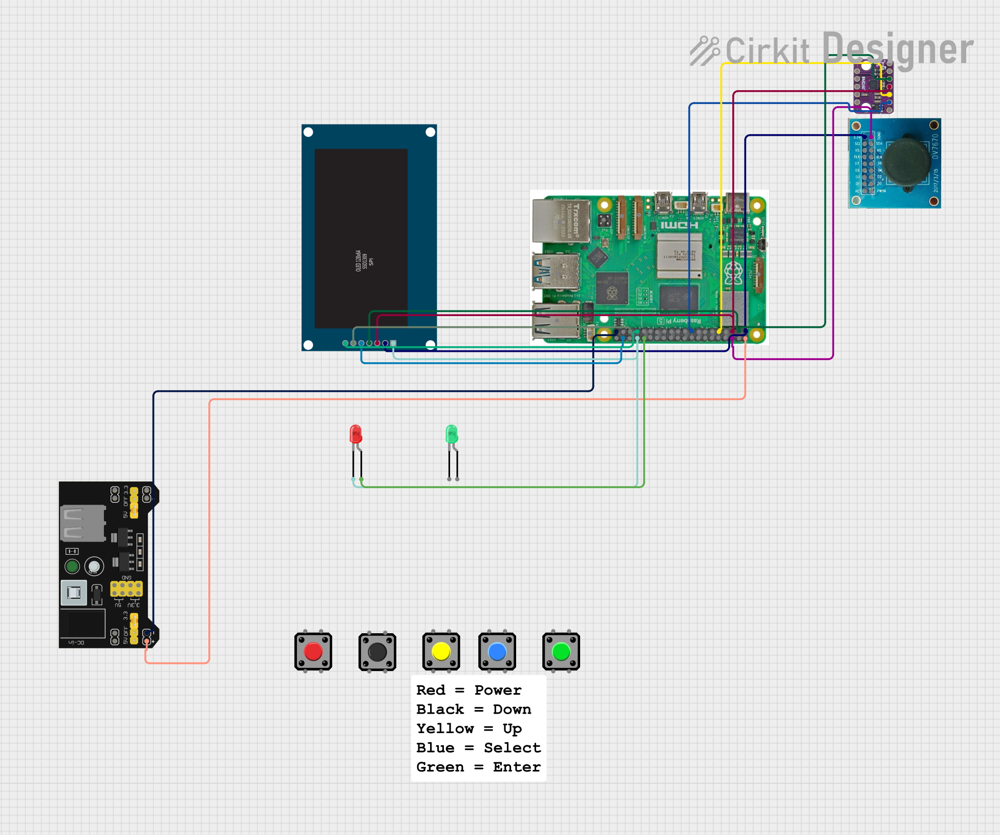
Circuit Documentation
Summary
This circuit involves a Raspberry Pi 5 as the central microcontroller, interfacing with various peripherals including an OV7670 camera module, a BMI160 accelerometer and gyroscope sensor, an MB102 breadboard power supply module, multiple pushbuttons, red and green LEDs, and a 2.42 inch 128x64 OLED display. The circuit is designed to demonstrate basic interfacing and control of these peripherals using the Raspberry Pi 5.
Component List
Raspberry Pi 5
- Description: A powerful single-board computer with multiple GPIO pins for interfacing with various peripherals.
- Pins: Type-C, Micro HDMI 1, Micro HDMI 2, Camera 1, Camera 2, PoE, Fan, PCIe, USB 3.0, USB 2.0, Ethernet, 5V, GND, 3.3v, GPIO 14, GPIO 15, GPIO 18, GPIO 23, GPIO 24, GPIO 25, GPIO 8, GPIO 7, GPIO 1, GPIO 12, GPIO 16, GPIO 20, GPIO 21, GPIO 2, GPIO 3, GPIO 4, GPIO 17, GPIO 27, GPIO 22, GPIO 10, GPIO 9, GPIO 11, GPIO 0, GPIO 5, GPIO 6, GPIO 13, GPIO 19, GPIO 26
OV7670
- Description: A camera module used for capturing images and video.
- Pins: RET, PWDN, D1, D0, D3, D2, D4, D5, D6, PLK, XLK, D7, VS, HS, SCL, SDA, 3.3V, DGND
BMI160 Accelerometer Gyro - 6DOF sensor
- Description: A 6 degrees of freedom sensor for measuring acceleration and gyroscopic data.
- Pins: SDX, SCX, INT1, INT2, OCS, SAO, CS, SDA, SCL, GND, 3V3, VIN
MB102 Breadboard Power Supply Module 3.3V/5V
- Description: A power supply module for providing 3.3V and 5V power to the breadboard.
- Pins: VCC, GND, 3.3V, 5V
Pushbutton
- Description: A simple pushbutton for user input.
- Pins: Pin 2, Pin 1, Pin 3, Pin 4
LED: Two Pin (red)
- Description: A red LED for visual indication.
- Pins: cathode, anode
LED: Two Pin (green)
- Description: A green LED for visual indication.
- Pins: cathode, anode
Tactile Switch Buttons - 12mm Square
- Description: A tactile switch button for user input.
- Pins: 3, 1, 4, 2
2.42 inch 128x64 OLED
- Description: An OLED display for visual output.
- Pins: GND, VCC, SCL, SDA, RES, DC, CS
Wiring Details
Raspberry Pi 5
- 5V connected to VCC of MB102 Breadboard Power Supply Module 3.3V/5V
- GND connected to DGND of OV7670
- GND connected to GND of MB102 Breadboard Power Supply Module 3.3V/5V
- 3.3v connected to 3.3V of OV7670 and VCC of 2.42 inch 128x64 OLED
- GPIO 12 connected to anode of LED: Two Pin (red)
- GND connected to cathode of LED: Two Pin (red) and GND of 2.42 inch 128x64 OLED
- GPIO 20 connected to RES of 2.42 inch 128x64 OLED
- GPIO 2 connected to SDA of BMI160 Accelerometer Gyro - 6DOF sensor and SDA of 2.42 inch 128x64 OLED
- GPIO 3 connected to SCL of BMI160 Accelerometer Gyro - 6DOF sensor and SCL of 2.42 inch 128x64 OLED
- GND connected to GND of BMI160 Accelerometer Gyro - 6DOF sensor
- 3.3v connected to 3V3 of BMI160 Accelerometer Gyro - 6DOF sensor
- GPIO 13 connected to CS of 2.42 inch 128x64 OLED
- GPIO 19 connected to DC of 2.42 inch 128x64 OLED
OV7670
- DGND connected to GND of Raspberry Pi 5
- 3.3V connected to 3.3v of Raspberry Pi 5
BMI160 Accelerometer Gyro - 6DOF sensor
- SDA connected to GPIO 2 of Raspberry Pi 5
- SCL connected to GPIO 3 of Raspberry Pi 5
- GND connected to GND of Raspberry Pi 5
- 3V3 connected to 3.3v of Raspberry Pi 5
MB102 Breadboard Power Supply Module 3.3V/5V
- VCC connected to 5V of Raspberry Pi 5
- GND connected to GND of Raspberry Pi 5
LED: Two Pin (red)
- anode connected to GPIO 12 of Raspberry Pi 5
- cathode connected to GND of Raspberry Pi 5
2.42 inch 128x64 OLED
- VCC connected to 3.3v of Raspberry Pi 5
- GND connected to GND of Raspberry Pi 5
- SDA connected to GPIO 2 of Raspberry Pi 5
- SCL connected to GPIO 3 of Raspberry Pi 5
- RES connected to GPIO 20 of Raspberry Pi 5
- CS connected to GPIO 13 of Raspberry Pi 5
- DC connected to GPIO 19 of Raspberry Pi 5
Documented Code
Raspberry Pi 5 Code (sketch.ino)
void setup() {
  // put your setup code here, to run once:

}

void loop() {
  // put your main code here, to run repeatedly:

}
Additional Documentation (documentation.txt)