
Pushbutton-Controlled Diode-Protected DC Motor and Bulb Circuit
View and Edit Project In Cirkit Designer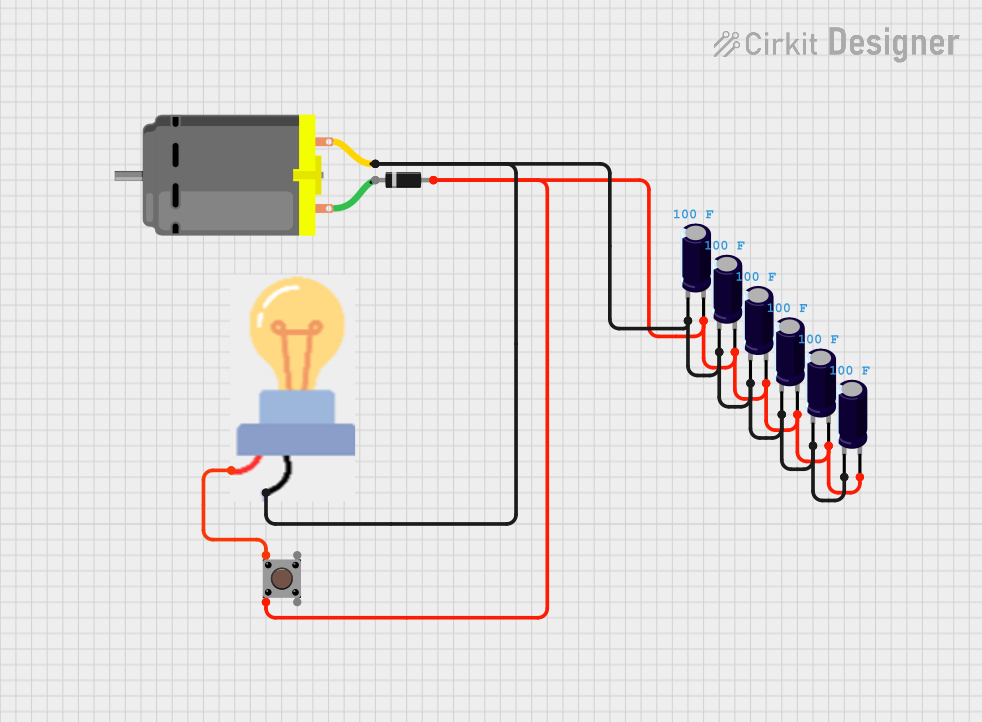
Circuit Documentation
Summary of the Circuit
This circuit appears to be a simple control circuit that includes a diode, multiple electrolytic capacitors, a pushbutton, a bulb, and a DC motor. The capacitors may be used for smoothing or filtering purposes in a power supply section. The diode is likely used for polarity protection or to ensure current flows in a single direction. The pushbutton controls the power to the bulb, and the DC motor is connected to the negative side of the power supply through the capacitors and to the ground of the bulb.
Component List
Diode
- Description: A semiconductor device that allows current to flow in one direction only.
- Pins: cathode, anode
Electrolytic Capacitor
- Description: A polarized capacitor with a high capacitance value.
- Pins: -, +
- Properties: Capacitance: 100 Farads
Bulb
- Description: An electric light source.
- Pins: GND, power
Pushbutton
- Description: A momentary switch that completes a circuit when pressed.
- Pins: Pin 3 (out), Pin 4 (out), Pin 1 (in), Pin 2 (in)
DC Motor
- Description: A machine that converts electrical energy into mechanical energy.
- Pins: pin 1, pin 2
Wiring Details
Diode
- Anode connected to the positive side of multiple Electrolytic Capacitors and Pin 2 (in) of the Pushbutton.
- Cathode is not connected in the provided net list.
Electrolytic Capacitors
- All + pins are interconnected and connected to the anode of the Diode and Pin 2 (in) of the Pushbutton.
- All - pins are interconnected and connected to the GND of the Bulb, pin 2 of the DC Motor.
Bulb
- GND connected to the negative side of multiple Electrolytic Capacitors.
- Power connected to Pin 1 (in) of the Pushbutton.
Pushbutton
- Pin 1 (in) connected to the power of the Bulb.
- Pin 2 (in) connected to the positive side of multiple Electrolytic Capacitors and the anode of the Diode.
- Pin 3 (out) and Pin 4 (out) are not connected in the provided net list.
DC Motor
- Pin 1 is not connected in the provided net list.
- Pin 2 connected to the negative side of multiple Electrolytic Capacitors.
Documented Code
No code has been provided for any microcontrollers in the circuit. If code becomes available, it should be documented in this section with appropriate comments and explanations for each function and routine.