Arduino and ESP32-Based Sensor Monitoring and Motor Control System
Circuit Documentation
Summary
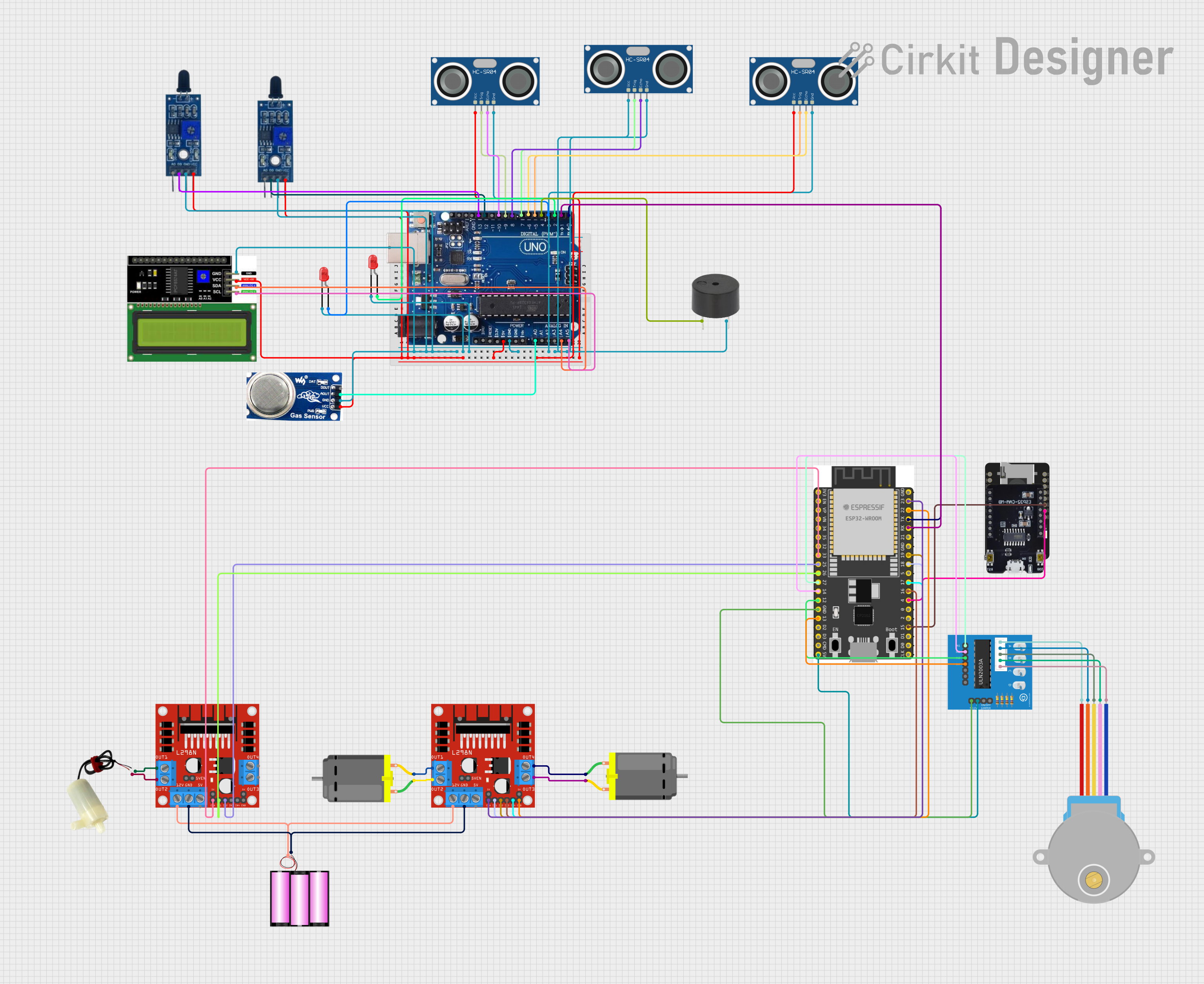
This circuit integrates various sensors, actuators, and microcontrollers to perform a range of functions. It includes flame and smoke detection, distance measurement, motor control, and visual feedback through LEDs and an LCD display. The circuit is powered by a 12V battery and regulated voltages for different components. The microcontrollers (Arduino Uno R3 and ESP32 variants) serve as the brains of the operation, interfacing with sensors and controlling actuators based on sensor inputs.
Component List
Microcontrollers
- Arduino Uno R3: A microcontroller board based on the ATmega328P, commonly used for building digital devices and interactive objects that can sense and control objects in the physical world.
- ESP32 - CAM: A small-sized ESP32-based module with support for a camera and microSD card, ideal for IoT applications.
- ESP 32 Wroom Dev Kit: A development board based on the ESP32 chip, suitable for a variety of IoT tasks.
Sensors
- Flame Sensor: Detects fire or other wavelengths of light that are similar to that produced by fire.
- Smoke Sensor: Detects the presence of smoke particles in the air, commonly used in fire alarm systems.
- HC-SR04 Ultrasonic Sensor: Measures distance by emitting ultrasonic waves and measuring the time taken for the echo to return.
- ESP32-CAM MB FLIP: An additional ESP32-CAM module, possibly for redundancy or additional viewpoint.
Actuators
- DC Motor: Converts electrical energy into mechanical motion.
- 5v mini water pump: An electric pump that moves water upon activation.
- 28BYJ-48 Stepper Motor: A small stepper motor that allows for precise control of angular or linear position, velocity, and acceleration.
- buzzer: An electromechanical component that produces sound.
Motor Drivers
- L298N DC motor driver: A high-power motor driver capable of driving inductive loads such as relays, solenoids, and DC and stepping motors.
- ULN2003A breakout board: A board that contains the ULN2003A transistor array, suitable for driving stepper motors.
Power
- battery 12v: Provides the power necessary to drive the motors and other components in the circuit.
Display
- LCD I2C Display: A liquid crystal display that communicates over the I2C protocol, used to display information to the user.
Indicators
- LED: Two Pin (red): A simple red light-emitting diode used for indication purposes.
Wiring Details
Microcontrollers
Arduino Uno R3
- Connected to various sensors and actuators through digital and analog pins.
- Interfaces with the LCD I2C Display via I2C communication pins (A4/SDA, A5/SCL).
- Communicates with the ESP 32 Wroom Dev Kit via serial pins (0/RX, 1/TX).
ESP32 - CAM
- Interacts with the ESP 32 Wroom Dev Kit through GPIO connections.
ESP 32 Wroom Dev Kit
- Controls the L298N DC motor drivers and ULN2003A breakout board through multiple GPIO pins.
- Powers the ULN2003A breakout board through the V5 pin.
- Shares a common ground with the ULN2003A breakout board.
Sensors
Flame Sensors
- Both sensors are powered by a common VCC line and share a common ground.
- Digital outputs (D0) are connected to the Arduino Uno R3 digital pins (12, 13).
Smoke Sensor
- Powered by a common VCC line and shares a common ground.
- Analog output (AO) is connected to the Arduino Uno R3 analog pin (A0).
HC-SR04 Ultrasonic Sensors
- All sensors are powered by a common VCC line and share a common ground.
- Trigger (TRIG) and Echo (ECHO) pins are connected to various digital pins on the Arduino Uno R3.
Actuators
DC Motors
- Connected to the L298N DC motor drivers for control.
5v mini water pump
- Controlled by the L298N DC motor driver.
28BYJ-48 Stepper Motor
- Connected to the ULN2003A breakout board.
buzzer
- Connected to the Arduino Uno R3 digital pin (4) and shares a common ground.
Motor Drivers
L298N DC motor drivers
- Powered by the 12V battery.
- Control connections from the ESP 32 Wroom Dev Kit.
- Drive the DC Motors and the 5v mini water pump.
ULN2003A breakout board
- Powered by the ESP 32 Wroom Dev Kit.
- Receives control signals from the ESP 32 Wroom Dev Kit.
- Drives the 28BYJ-48 Stepper Motor.
Power
- battery 12v
- Provides power to the L298N DC motor drivers.
Display
- LCD I2C Display
- Powered by a common VCC line and shares a common ground.
- Communicates with the Arduino Uno R3 via I2C protocol.
Indicators
- LED: Two Pin (red)
- Anodes are connected to the Arduino Uno R3 digital pins (2, 3).
- Cathodes share a common ground.
Documented Code
No code was provided for the microcontrollers in the circuit. The documentation of the code would typically include descriptions of the functions, algorithms, and routines written for the microcontrollers to interface with the sensors, control the actuators, and communicate with other devices. It would also include any libraries used, the setup and loop functions, and any interrupt service routines or callbacks.