Cirkit Designer
Your all-in-one circuit design IDE
Home /
Project Documentation
Raspberry Pi Controlled LED Array with Resistors
Circuit Documentation
Summary
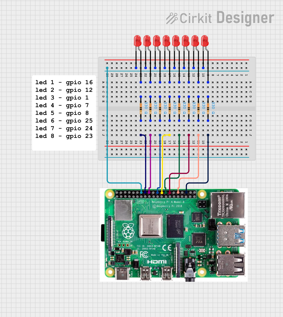
This circuit consists of multiple red LEDs connected to a Raspberry Pi 4b through resistors. Each LED is connected in series with a 330 Ohm resistor, and the resistors are connected to various GPIO pins on the Raspberry Pi. The cathodes of all LEDs are connected to the ground (GND) pin of the Raspberry Pi.
Component List
LED: Two Pin (red)
- Description: A standard red LED with two pins: anode and cathode.
- Pins: cathode, anode
Resistor
- Description: A 330 Ohm resistor used to limit the current through the LEDs.
- Pins: pin1, pin2
- Properties:
- Resistance: 330 Ohms
Raspberry Pi 4b
- Description: A single-board computer with multiple GPIO pins for interfacing with external components.
- Pins: 5V, 3V3, GPIO 2(SDA), GPIO 3(SCL), GPIO 4(GPCLK0), GND, GPIO 14(TXD), GPIO 15(RXD), GPIO 17, GPIO 27, GPIO 22, GPIO 10(MOSI), GPIO 9(MISO), GPIO 11(SCLK), GPIO 0(ID_SD), GPIO 5, GPIO 6, GPIO 13(PWM1), GPIO 19(PCM_FS), GPIO 26, GPIO 18(PCM_CLK), GPIO 23, GPIO 24, GPIO 25, GPIO 8(CE0), GPIO 7(CE1), GPIO 1(ID_SC), GPIO 12(PWM0), GPIO 16, GPIO 20(PCM_DIN), GPIO 21(PCM_DOUT), USB-C POWER PORT 5V/3A, MICRO HDMI PORT, 4 POLE STEREO AUDIO, 2X USB 2.0, 2X USB 3.O, GIGABIT ETHERNET
Wiring Details
LED: Two Pin (red)
- Anode connected to pin1 of Resistor
- Cathode connected to GND of Raspberry Pi 4b
Resistor
- Pin1 connected to anode of LED
- Pin2 connected to various GPIO pins of Raspberry Pi 4b
Raspberry Pi 4b
- GPIO 16 connected to pin2 of Resistor
- GPIO 12(PWM0) connected to pin2 of Resistor
- GPIO 1(ID_SC) connected to pin2 of Resistor
- GPIO 7(CE1) connected to pin2 of Resistor
- GPIO 8(CE0) connected to pin2 of Resistor
- GPIO 25 connected to pin2 of Resistor
- GPIO 24 connected to pin2 of Resistor
- GPIO 23 connected to pin2 of Resistor
- GND connected to cathode of all LEDs
Detailed Wiring for Each LED and Resistor Pair
LED 1
- Anode connected to pin1 of Resistor
- Cathode connected to GND of Raspberry Pi 4b
- Resistor pin2 connected to GPIO 16 of Raspberry Pi 4b
LED 2
- Anode connected to pin1 of Resistor
- Cathode connected to GND of Raspberry Pi 4b
- Resistor pin2 connected to GPIO 12(PWM0) of Raspberry Pi 4b
LED 3
- Anode connected to pin1 of Resistor
- Cathode connected to GND of Raspberry Pi 4b
- Resistor pin2 connected to GPIO 1(ID_SC) of Raspberry Pi 4b
LED 4
- Anode connected to pin1 of Resistor
- Cathode connected to GND of Raspberry Pi 4b
- Resistor pin2 connected to GPIO 7(CE1) of Raspberry Pi 4b
LED 5
- Anode connected to pin1 of Resistor
- Cathode connected to GND of Raspberry Pi 4b
- Resistor pin2 connected to GPIO 8(CE0) of Raspberry Pi 4b
LED 6
- Anode connected to pin1 of Resistor
- Cathode connected to GND of Raspberry Pi 4b
- Resistor pin2 connected to GPIO 25 of Raspberry Pi 4b
LED 7
- Anode connected to pin1 of Resistor
- Cathode connected to GND of Raspberry Pi 4b
- Resistor pin2 connected to GPIO 24 of Raspberry Pi 4b
LED 8
- Anode connected to pin1 of Resistor
- Cathode connected to GND of Raspberry Pi 4b
- Resistor pin2 connected to GPIO 23 of Raspberry Pi 4b
Code
No code is provided for this circuit.