Cirkit Designer
Your all-in-one circuit design IDE
Home /
Project Documentation
Arduino UNO Based Portable Digital Weighing Scale with LCD and Audio-Visual Indicators
Circuit Documentation
Summary
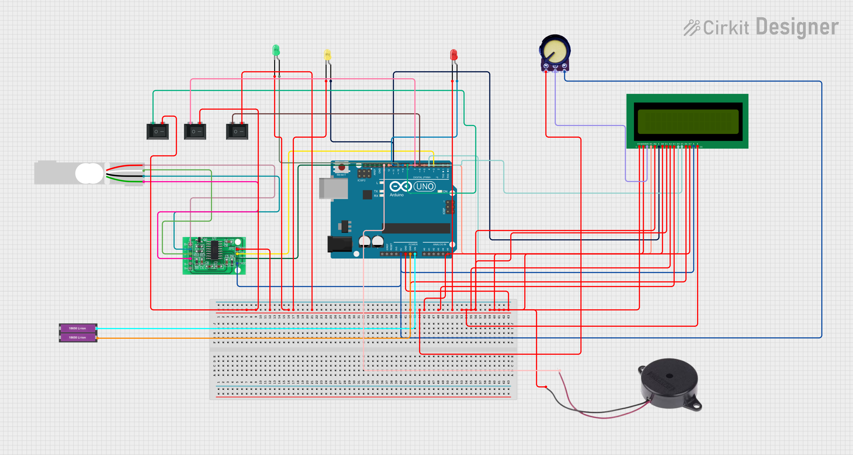
This circuit integrates various components controlled by an Arduino UNO microcontroller. It includes a load cell interfaced through an HX711 bridge sensor interface for weight measurement, a set of LEDs for status indication, a buzzer for audio feedback, an LCD for data display, and multiple rocker switches for user input. The circuit is powered by a pair of 18650 Li-ion batteries. The Arduino UNO manages the interaction between these components, processes sensor data, and controls the output devices based on the programmed logic.
Component List
Arduino UNO
- Microcontroller board based on the ATmega328P
- It has 14 digital input/output pins, 6 analog inputs, a 16 MHz quartz crystal, a USB connection, a power jack, an ICSP header, and a reset button.
HX711 - Bridge Sensor Interface
- A precision 24-bit analog-to-digital converter (ADC) designed for weigh scales and industrial control applications to interface directly with a bridge sensor.
Buzzer
- An electromechanical component that produces a continuous or intermittent sound when an electrical signal is applied.
LEDs (Red, Green, Yellow)
- Light Emitting Diodes used as visual indicators in the circuit.
Load Cell - Red/white/black/green
- A transducer that converts force into an electrical signal and is used in this circuit for weight measurement.
16X2 LCD
- A liquid crystal display capable of displaying 16 characters per line across 2 lines, used for data output.
Rocker Switch (SPST)
- A single pole single throw switch used to control the power or mode of operation in the circuit.
Potentiometer
- A three-terminal resistor with a rotating contact that forms an adjustable voltage divider.
18650 Li-ion Battery x 2
- A pair of rechargeable batteries providing the power source for the circuit.
Wiring Details
Arduino UNO
GNDconnected to common ground net.5Vconnected to Potentiometer VCC, 16X2 LCD A, and HX711 3.3/3.5V Supply.Vinconnected to 18650 Li-ion Battery +.D13connected to Buzzer POSITIVE.D12connected to 16X2 LCD RS.D11connected to 16X2 LCD E and LED (Yellow) anode.D10connected to LED (Green) anode.D9connected to LED (Red) anode.D8connected to Rocker Switch (SPST) pin 1.D7connected to Rocker Switch (SPST) pin 1.D6connected to Rocker Switch (SPST) pin 1.D4connected to 16X2 LCD D4 and D5.D3connected to HX711 DATA (OUT).D2connected to HX711 SCK - CLOCK (IN).
HX711 - Bridge Sensor Interface
E+,A-,E-,A+connected to corresponding Load Cell pins.GND - GROUNDconnected to common ground net.DATA (OUT)connected to Arduino UNO D3.SCK - CLOCK (IN)connected to Arduino UNO D2.3.3/3.5V Supplyconnected to Arduino UNO 5V.
Buzzer
POSITIVEconnected to Arduino UNO D13.NEGATIVEconnected to common ground net.
LEDs (Red, Green, Yellow)
cathodeconnected to common ground net.anodeof Red connected to Arduino UNO D9.anodeof Green connected to Arduino UNO D10.anodeof Yellow connected to Arduino UNO D11.
Load Cell - Red/white/black/green
E+,A-,E-,A+connected to corresponding HX711 pins.
16X2 LCD
VSSconnected to common ground net.VDDconnected to Arduino UNO 5V.V0connected to Potentiometer Output.RSconnected to Arduino UNO D12.RWconnected to common ground net.Econnected to Arduino UNO D11.D0-D7connected to common ground net.Aconnected to Arduino UNO 5V.Kconnected to common ground net.
Rocker Switch (SPST)
- Pin
1of each switch connected to Arduino UNO D6, D7, D8 respectively. - Pin
2of each switch connected to common ground net.
Potentiometer
GNDconnected to common ground net.Outputconnected to 16X2 LCD V0.VCCconnected to Arduino UNO 5V.
18650 Li-ion Battery x 2
+connected to Arduino UNO Vin.-connected to common ground net.
Documented Code
Arduino UNO Code (sketch.ino)
void setup() {
  // put your setup code here, to run once:

}

void loop() {
  // put your main code here, to run repeatedly:

}
Note: The provided code is a template and does not contain any functional logic. It needs to be populated with the specific setup and loop code to control the circuit components as per the requirements.