
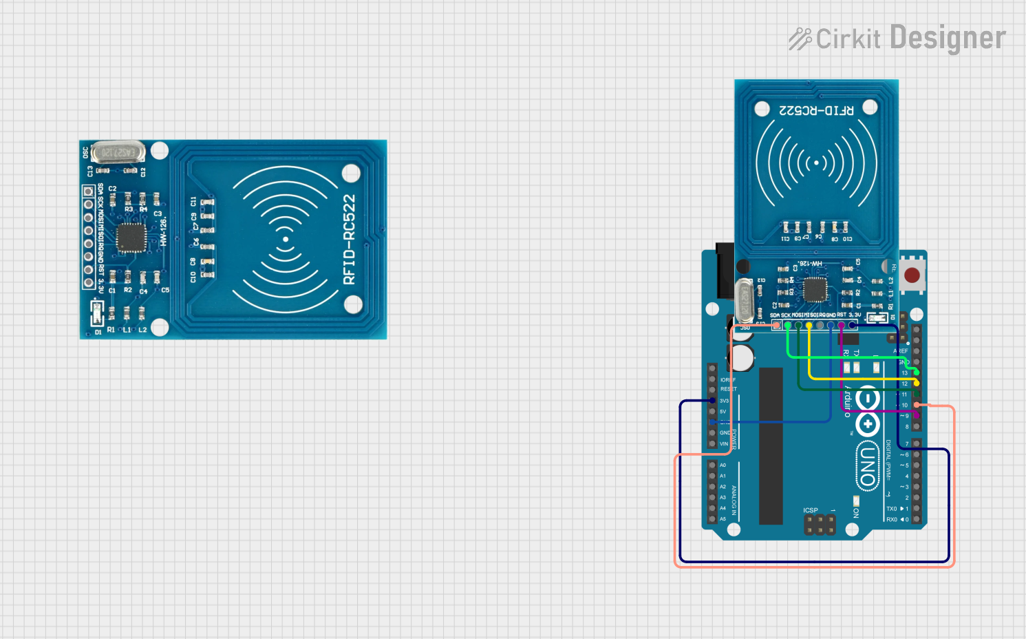
RFID Reader Circuit Documentation
Summary
This document describes a circuit designed to interface an Arduino UNO with an RFID-RC522 module. The purpose of the circuit is to read RFID tags and output their unique identifiers (UIDs) to the serial monitor. The Arduino UNO acts as the central processing unit, controlling the RFID-RC522 module via the SPI (Serial Peripheral Interface) bus. The provided code initializes the RFID module and continuously polls for the presence of RFID tags. When a tag is detected, its UID is printed to the serial monitor.
Component List
Arduino UNO
- Description: A microcontroller board based on the ATmega328P.
- Purpose: Serves as the main controller for the RFID reader system, managing communication with the RFID-RC522 module and handling data processing.
RFID-RC522 Module
- Description: An RFID reader/writer module that operates at 13.56 MHz.
- Purpose: Reads the UID of RFID tags and communicates the information to the Arduino UNO.
Wiring Details
Arduino UNO
- 3.3V supplies power to the RFID-RC522 module.
- GND is connected to the ground of the RFID-RC522 module to complete the power circuit.
- D13 (SCK) is connected to the SCK pin of the RFID-RC522 module for SPI clock.
- D12 (MISO) is connected to the MISO pin of the RFID-RC522 module for SPI Master In Slave Out.
- D11 (MOSI) is connected to the MOSI pin of the RFID-RC522 module for SPI Master Out Slave In.
- D10 (SS) is connected to the SDA pin of the RFID-RC522 module for SPI Slave Select.
- D9 (RST) is connected to the RST pin of the RFID-RC522 module for reset control.
RFID-RC522 Module
- VCC (3.3V) receives power from the 3.3V output of the Arduino UNO.
- RST is connected to digital pin D9 on the Arduino UNO for reset control.
- GND is connected to the ground on the Arduino UNO.
- IRQ is not used in this circuit.
- MISO is connected to digital pin D12 on the Arduino UNO for SPI communication.
- MOSI is connected to digital pin D11 on the Arduino UNO for SPI communication.
- SCK is connected to digital pin D13 on the Arduino UNO for SPI communication.
- SDA is connected to digital pin D10 on the Arduino UNO for SPI communication.
Documented Code
/*
 * This Arduino Sketch interfaces with an RFID-RC522 module using an Arduino UNO.
 * It initializes the RFID module and continuously checks for RFID tags.
 * When a tag is detected, its UID is printed to the serial monitor.
 */

#include <SPI.h>
#include <MFRC522.h>

#define RST_PIN 9 // Configured to pin D9
#define SS_PIN 10 // Configured to pin D10

MFRC522 rfid(SS_PIN, RST_PIN); // Create MFRC522 instance

void setup() {
  Serial.begin(9600); // Initialize serial communications
  SPI.begin(); // Initialize SPI bus
  rfid.PCD_Init(); // Initialize RFID reader
  Serial.println("Scan an RFID tag...");
}

void loop() {
  // Look for new cards
  if (!rfid.PICC_IsNewCardPresent()) {
    return;
  }
  // Select one of the cards
  if (!rfid.PICC_ReadCardSerial()) {
    return;
  }
  // Print UID of the card
  Serial.print("UID tag: ");
  for (byte i = 0; i < rfid.uid.size; i++) {
    Serial.print(rfid.uid.uidByte[i] < 0x10 ? " 0" : " ");
    Serial.print(rfid.uid.uidByte[i], HEX);
  }
  Serial.println();
  // Halt PICC
  rfid.PICC_HaltA();
  // Stop encryption on PCD
  rfid.PCD_StopCrypto1();
}
This code is written for the Arduino platform and is intended to be uploaded to the Arduino UNO microcontroller. It includes the necessary libraries for interfacing with the RFID-RC522 module and contains the main logic for initializing the RFID reader, detecting RFID tags, and printing their UIDs to the serial monitor.