Arduino Mega 2560-Based Multi-Sensor Vehicle Tracker with GSM and GPS
Circuit Documentation
Summary
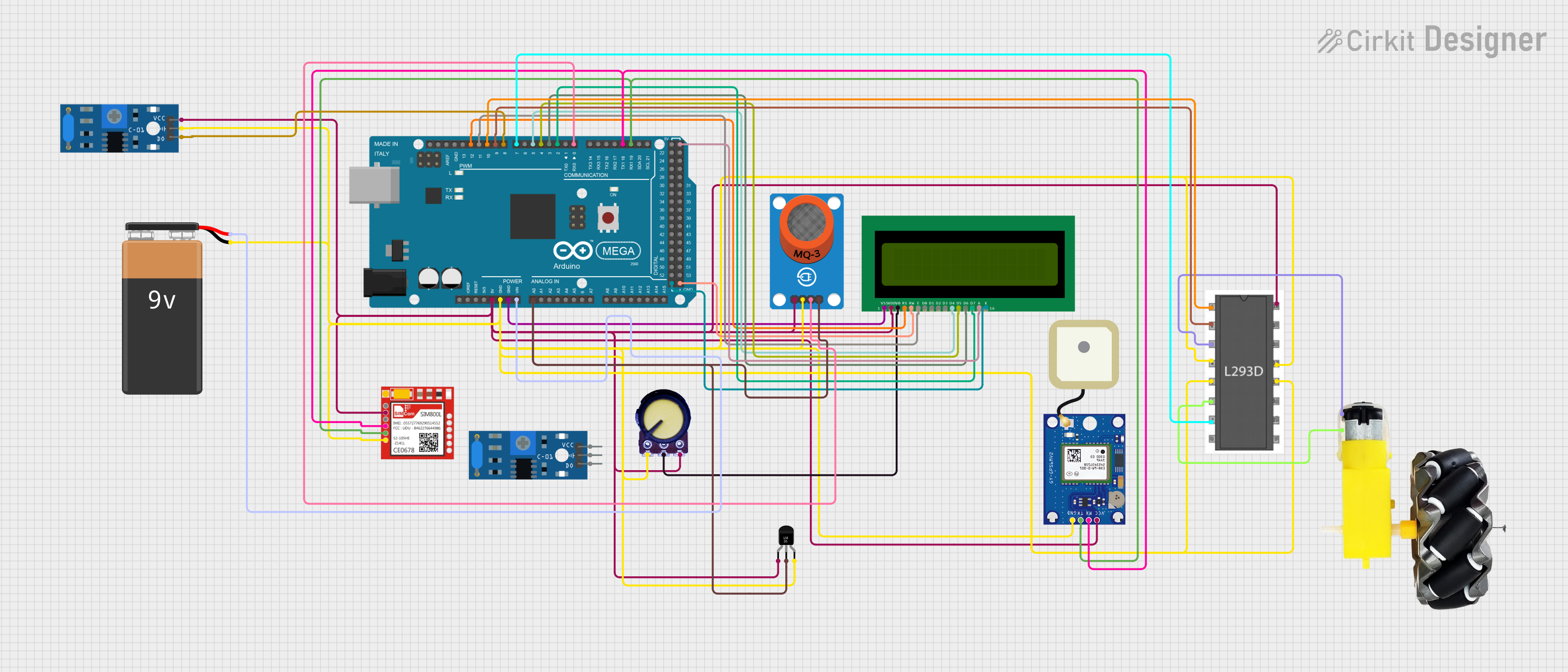
This document provides a detailed overview of a circuit designed to interface various sensors and modules with an Arduino Mega 2560 microcontroller. The circuit includes components for sensing alcohol levels (MQ-3 Breakout), displaying information (16X2 LCD), communication (Sim800l), GPS tracking (GPS NEO-6M V2), motor control (l293d), temperature sensing (LM35), user input (Potentiometer), and vibration detection (SW-420 Vibration Sensor). A 9V battery powers the system.
Component List
Arduino Mega 2560
- Microcontroller board based on the ATmega2560
- Provides 54 digital I/O pins and 16 analog inputs
MQ-3 Breakout
- Alcohol gas sensor module
- Provides both analog and digital outputs
16X2 LCD
- Alphanumeric Liquid Crystal Display
- Displays 2 lines of 16 characters
Sim800l
- GSM/GPRS module
- Enables cellular communication for the circuit
GPS NEO-6M V2
- GPS module
- Provides location data to the circuit
l293d
- Motor driver IC
- Controls up to two DC motors
Temperature Sensor (LM35)
- Precision centigrade temperature sensor
- Provides analog output proportional to temperature
Potentiometer
- Variable resistor
- Provides analog input to adjust LCD contrast
Motor and Wheels
- DC motor with attached wheels
- Provides motion to the system
9V Battery
- Power source for the circuit
SW-420 Vibration Sensor
- Vibration detection module
- Provides digital output upon detecting vibration
Wiring Details
Arduino Mega 2560
5Vconnected to VCC of various components for powerGNDconnected to GND of various components for common groundVINconnected to the positive terminal of the 9V BatteryA0connected to analog outputs of MQ-3 Breakout and LM35D19/RX1connected to TX of GPS NEO-6M V2 and TXD of Sim800lD18/TX1connected to RX of GPS NEO-6M V2 and RXD of Sim800lD0 RX0connected to digital output of MQ-3 BreakoutD2 PWMtoD7 PWMconnected to data pinsD7toD4of 16X2 LCDD10 PWMconnected toEnable 1,2of l293dD9 PWMconnected toInput 1of l293dD8 PWMconnected to digital output of SW-420 Vibration SensorD7 PWMconnected toInput 2of l293dD11 PWMconnected toEof 16X2 LCDD12 PWMconnected toRSof 16X2 LCD
MQ-3 Breakout
VCCandGNDfor power supplyAOconnected toA0of Arduino Mega 2560 for analog outputDOconnected toD0 RX0of Arduino Mega 2560 for digital output
16X2 LCD
VDDandVSSfor power supply and groundV0connected to output of Potentiometer for contrast adjustmentRS,E,D4toD7connected toD12 PWMtoD5 PWMof Arduino Mega 2560 for data/command interfaceAandKfor backlight anode and cathode
Sim800l
VCCandGNDfor power supplyTXDconnected toD19/RX1of Arduino Mega 2560 for transmitting dataRXDconnected toD18/TX1of Arduino Mega 2560 for receiving data
GPS NEO-6M V2
VCCandGNDfor power supplyTXconnected toD19/RX1of Arduino Mega 2560 for transmitting dataRXconnected toD18/TX1of Arduino Mega 2560 for receiving data
l293d
Vcc1andGNDfor logic power supply and groundInput 1andInput 2connected toD9 PWMandD7 PWMof Arduino Mega 2560 for motor control signalsEnable 1,2connected toD10 PWMof Arduino Mega 2560 for enabling motor driver channelsOutput 1andOutput 2connected tovccandGNDof Motor and Wheels for motor output
Temperature Sensor (LM35)
+VsandGNDfor power supplyVoutconnected toA0of Arduino Mega 2560 for temperature reading
Potentiometer
VCCandGNDfor power supplyOutputconnected toV0of 16X2 LCD for contrast control
Motor and Wheels
vccandGNDconnected toOutput 1andOutput 2of l293d for receiving motor power
SW-420 Vibration Sensor
vccandGroundfor power supplyDigital outputconnected toD8 PWMof Arduino Mega 2560 for vibration detection
Documented Code
Arduino Mega 2560 Code (sketch.ino)
void setup() {
  // put your setup code here, to run once:

}

void loop() {
  // put your main code here, to run repeatedly:

}
This code template provides the basic structure for the Arduino sketch. The setup() function is called once when the program starts and is used to initialize settings. The loop() function runs continuously after setup() has finished and is where the main logic of the program will be implemented.