
Arduino UNO R4 WiFi Smart Irrigation and Environmental Monitoring System
View and Edit Project In Cirkit Designer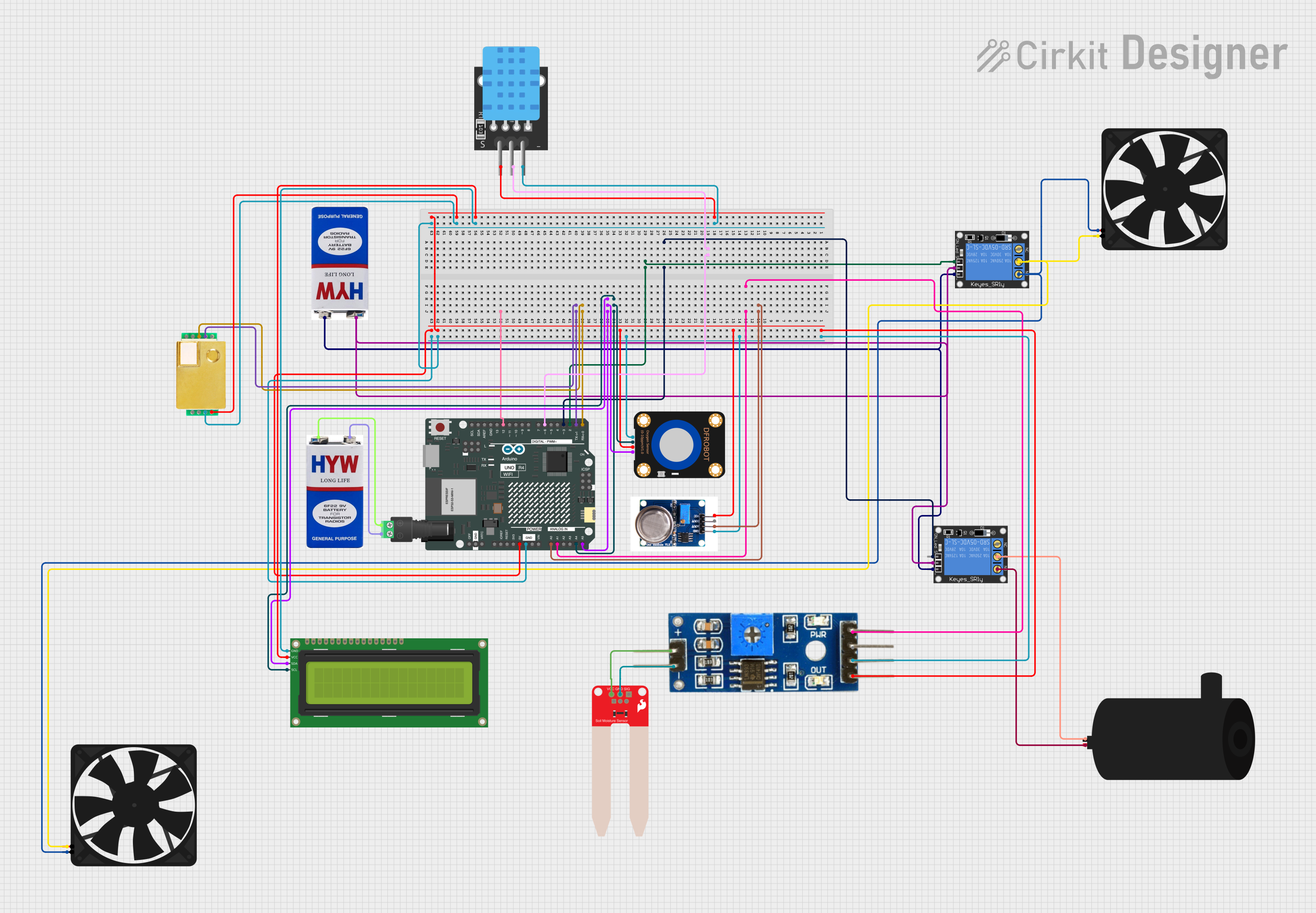
Circuit Documentation
Summary
This document provides a detailed overview of a circuit that integrates various sensors, relays, and actuators with an Arduino UNO R4 WiFi microcontroller. The circuit is designed to monitor environmental parameters such as soil moisture, temperature, and gas concentrations, and to control devices like fans and water pumps based on sensor readings.
Component List
Arduino UNO R4 WiFi
- Description: A microcontroller board based on the ATmega328P, featuring built-in WiFi capabilities.
- Pins: OFF, GND, VRTC, IIC0_SCL, IIC0_SDA, 3V3, GPIO 41, GPIO 0, GPIO 42, GPIO 43, GPIO 44, BOOT, IOREF, RESET, 5V, VIN, A0, A1, A2, A3, A4, A5, RSPCKA, CIPO, COPI, D0/RX, D1/TX, D2, D3, D4, D5, D6, D7, D8, D9, D10, D11, D12, D13, AREF, SDA, SCL
9V Battery
- Description: A standard 9V battery used to power the circuit.
- Pins: +, -
1-Channel Relay (5V 10A)
- Description: A relay module used to control high-power devices.
- Pins: NC, signal, C, power, NO, ground
Water Pump
- Description: A small water pump used for irrigation purposes.
- Pins: positive, negative
DFRobot Oxygen Sensor
- Description: A sensor used to measure oxygen concentration.
- Pins: Pin 1, Pin 2, Pin 3, Pin 4
Soil Moisture Module
- Description: A module used to measure soil moisture levels.
- Pins: positive, negative, Analog, Digital, Ground, VCC
SparkFun Soil Moisture Sensor
- Description: A sensor used to measure soil moisture levels.
- Pins: VCC, GND, SIG
2.1mm Barrel Jack with Terminal Block
- Description: A barrel jack used to connect the 9V battery to the circuit.
- Pins: POS, NEG
MQ131
- Description: A gas sensor used to measure ozone concentration.
- Pins: GND, AOUT, DOUT, VCC
MH-Z19B
- Description: A sensor used to measure CO2 concentration.
- Pins: HD, TX, RX, V0, PWM, GND, Vin
TEMP
- Description: A temperature sensor.
- Pins: 5V, D3, GND
Fan
- Description: A small fan used for ventilation.
- Pins: GND, 5V
16x2 I2C LCD
- Description: A 16x2 character LCD with I2C interface.
- Pins: GND, VCC, SDA, SCL
Wiring Details
Arduino UNO R4 WiFi
- A0: Connected to MQ131 (AOUT)
- A1: Connected to Soil Moisture Module (Analog)
- A4: Connected to DFRobot Oxygen Sensor (Pin 2) and 16x2 I2C LCD (SCL)
- A5: Connected to DFRobot Oxygen Sensor (Pin 4) and 16x2 I2C LCD (SDA)
- D0/RX: Connected to MH-Z19B (TX)
- D1/TX: Connected to MH-Z19B (RX)
- D2: Connected to 1-Channel Relay (signal)
- D3: Connected to 1-Channel Relay (signal)
- D6: Connected to TEMP (D3)
- 5V: Connected to Soil Moisture Module (VCC), MQ131 (VCC), DFRobot Oxygen Sensor (Pin 3), TEMP (5V), 16x2 I2C LCD (VCC), MH-Z19B (Vin)
- GND: Connected to Soil Moisture Module (Ground), MQ131 (GND), DFRobot Oxygen Sensor (Pin 1), TEMP (GND), 16x2 I2C LCD (GND), MH-Z19B (GND)
9V Battery
- +: Connected to 2.1mm Barrel Jack with Terminal Block (POS)
- -: Connected to 2.1mm Barrel Jack with Terminal Block (NEG)
1-Channel Relay (5V 10A)
- signal: Connected to Arduino UNO R4 WiFi (D2)
- signal: Connected to Arduino UNO R4 WiFi (D3)
- power: Connected to 9V Battery (+)
- ground: Connected to 9V Battery (-)
- C: Connected to Fan (GND) and Fan (5V)
- NO: Connected to Fan (5V) and Fan (GND)
- C: Connected to Water Pump (negative)
- NO: Connected to Water Pump (positive)
Water Pump
- positive: Connected to 1-Channel Relay (NO)
- negative: Connected to 1-Channel Relay (C)
DFRobot Oxygen Sensor
- Pin 2: Connected to Arduino UNO R4 WiFi (A4)
- Pin 4: Connected to Arduino UNO R4 WiFi (A5)
- Pin 3: Connected to Arduino UNO R4 WiFi (5V)
- Pin 1: Connected to Arduino UNO R4 WiFi (GND)
Soil Moisture Module
- Analog: Connected to Arduino UNO R4 WiFi (A1)
- VCC: Connected to Arduino UNO R4 WiFi (5V)
- Ground: Connected to Arduino UNO R4 WiFi (GND)
SparkFun Soil Moisture Sensor
- VCC: Connected to Soil Moisture Module (positive)
- GND: Connected to Soil Moisture Module (negative)
2.1mm Barrel Jack with Terminal Block
- POS: Connected to 9V Battery (+)
- NEG: Connected to 9V Battery (-)
MQ131
- AOUT: Connected to Arduino UNO R4 WiFi (A0)
- VCC: Connected to Arduino UNO R4 WiFi (5V)
- GND: Connected to Arduino UNO R4 WiFi (GND)
MH-Z19B
- TX: Connected to Arduino UNO R4 WiFi (D0/RX)
- RX: Connected to Arduino UNO R4 WiFi (D1/TX)
- Vin: Connected to Arduino UNO R4 WiFi (5V)
- GND: Connected to Arduino UNO R4 WiFi (GND)
TEMP
- D3: Connected to Arduino UNO R4 WiFi (D6)
- 5V: Connected to Arduino UNO R4 WiFi (5V)
- GND: Connected to Arduino UNO R4 WiFi (GND)
Fan
- GND: Connected to 1-Channel Relay (C)
- 5V: Connected to 1-Channel Relay (NO)
- GND: Connected to 1-Channel Relay (NO)
- 5V: Connected to 1-Channel Relay (C)
16x2 I2C LCD
- SCL: Connected to Arduino UNO R4 WiFi (A4)
- SDA: Connected to Arduino UNO R4 WiFi (A5)
- VCC: Connected to Arduino UNO R4 WiFi (5V)
- GND: Connected to Arduino UNO R4 WiFi (GND)
Documented Code
Arduino UNO R4 WiFi Code
void setup() {
  // put your setup code here, to run once:

}

void loop() {
  // put your main code here, to run repeatedly:

}
This code is a basic template for the Arduino UNO R4 WiFi. The setup function is used to initialize any settings or configurations, and the loop function contains the main logic that runs repeatedly. You can add your specific logic to read sensor data and control the relays and actuators based on the sensor readings.