
Circuit Documentation
Summary
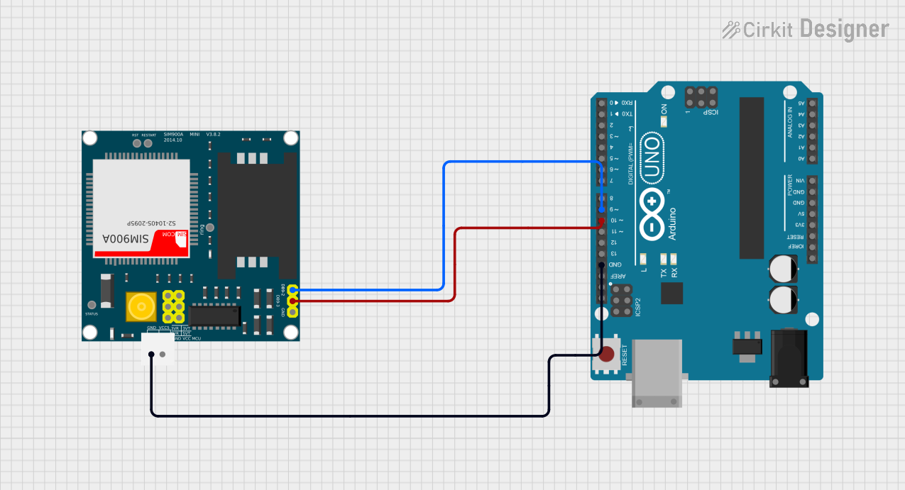
This document provides a detailed overview of a circuit that integrates an Arduino UNO microcontroller with a SIM900A GSM module. The Arduino UNO is used to control the SIM900A module, enabling GSM communication. The document includes a list of components, wiring details, and the embedded code used in the microcontroller.
Component List
Arduino UNO
- Description: A microcontroller board based on the ATmega328P.
- Pins: UNUSED, IOREF, Reset, 3.3V, 5V, GND, Vin, A0, A1, A2, A3, A4, A5, SCL, SDA, AREF, D13, D12, D11, D10, D9, D8, D7, D6, D5, D4, D3, D2, D1, D0, +, -
SIM900A
- Description: A GSM module used for communication over a GSM network.
- Pins: GND, DB9-3 (RXD), DB9-2 (TXD), 5V, 3VR, 5VR, 3VT, 5VT, VCC, Ring, RESTART, RESET, STATUS
Wiring Details
Arduino UNO
- GND: Connected to GND of SIM900A
- D10: Connected to DB9-3 (RXD) of SIM900A
- D9: Connected to DB9-2 (TXD) of SIM900A
SIM900A
- GND: Connected to GND of Arduino UNO
- DB9-3 (RXD): Connected to D10 of Arduino UNO
- DB9-2 (TXD): Connected to D9 of Arduino UNO
Code Documentation
Arduino UNO Code
void setup() {
  // put your setup code here, to run once:

}

void loop() {
  // put your main code here, to run repeatedly:

}
This code is a basic template for the Arduino UNO. The setup() function is where you initialize your settings, and the loop() function is where the main code runs repeatedly. Currently, the code does not perform any specific operations and serves as a starting point for further development.
This document provides a comprehensive overview of the circuit, including the components used, their wiring, and the initial code for the Arduino UNO. This should serve as a solid foundation for further development and testing of the circuit.