
Arduino Nano and SIM800L Based Battery-Powered GSM Communication System with Keypad Input
View and Edit Project In Cirkit Designer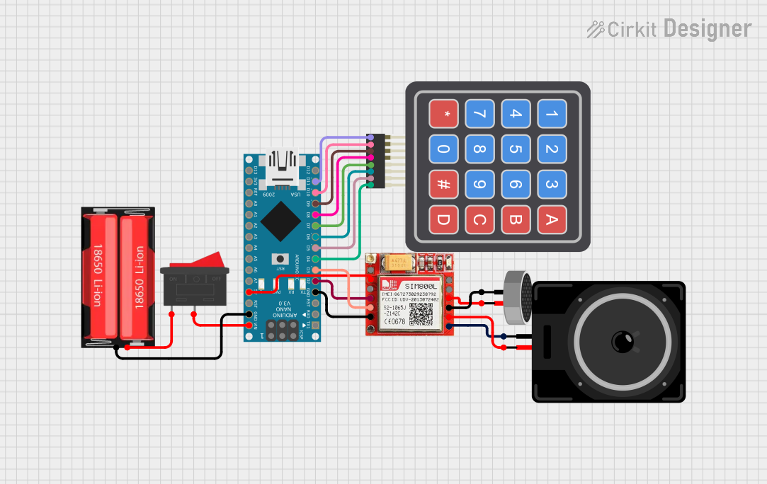
Circuit Documentation
Summary
This circuit is designed to interface an Arduino Nano with a SIM800L GSM module, a 4x4 Keypad, a condenser microphone, and a loudspeaker. The circuit allows for sending and receiving SMS, making and receiving calls, and interacting with the user through the keypad. The Arduino Nano serves as the main controller, handling communication with the SIM800L and processing user inputs from the keypad.
Component List
Arduino Nano
- Description: A small, complete, and breadboard-friendly board based on the ATmega328P.
- Pins: D1/TX, D0/RX, RESET, GND, D2, D3, D4, D5, D6, D7, D8, D9, D10, D11/MOSI, D12/MISO, VIN, 5V, A7, A6, A5, A4, A3, A2, A1, A0, AREF, 3V3, D13/SCK
18650 Li-Ion Battery
- Description: A rechargeable lithium-ion battery commonly used in portable electronics.
- Pins: Positive, Negative
Rocker Switch
- Description: A switch that can be toggled between an on and off state.
- Pins: 1, 2
Condenser Microphone
- Description: A type of microphone that uses a capacitor to convert sound into an electrical signal.
- Pins: pin1, pin2
Loudspeaker
- Description: A device that converts electrical signals into sound.
- Pins: pin1, pin2
4x4 Keypad (Simulator)
- Description: A matrix keypad with 4 rows and 4 columns, used for user input.
- Pins: R1, C4, R2, C2, R3, R4, C1, C3
SIM800L
- Description: A GSM/GPRS module that allows for communication over cellular networks.
- Pins: NET, VCC, RST, RXD, TXD, GND, RING, DTR, MIC+, MIC-, SPK+, SPK-
Wiring Details
Arduino Nano
- GND connected to GND of SIM800L
- D2 connected to RXD of SIM800L
- D3 connected to TXD of SIM800L
- D4 connected to C4 of 4x4 Keypad
- D5 connected to C3 of 4x4 Keypad
- D6 connected to C2 of 4x4 Keypad
- D7 connected to C1 of 4x4 Keypad
- D8 connected to R4 of 4x4 Keypad
- D9 connected to R3 of 4x4 Keypad
- D10 connected to R2 of 4x4 Keypad
- D11/MOSI connected to R1 of 4x4 Keypad
- VIN connected to 2 of Rocker Switch
- GND connected to Negative of 18650 Li-Ion Battery
- 5V connected to VCC of SIM800L
18650 Li-Ion Battery
- Positive connected to 1 of Rocker Switch
- Negative connected to GND of Arduino Nano
Rocker Switch
- 1 connected to Positive of 18650 Li-Ion Battery
- 2 connected to VIN of Arduino Nano
Condenser Microphone
- pin1 connected to MIC- of SIM800L
- pin2 connected to MIC+ of SIM800L
Loudspeaker
- pin1 connected to SPK- of SIM800L
- pin2 connected to SPK+ of SIM800L
4x4 Keypad (Simulator)
- C4 connected to D4 of Arduino Nano
- C3 connected to D5 of Arduino Nano
- C2 connected to D6 of Arduino Nano
- C1 connected to D7 of Arduino Nano
- R4 connected to D8 of Arduino Nano
- R3 connected to D9 of Arduino Nano
- R2 connected to D10 of Arduino Nano
- R1 connected to D11/MOSI of Arduino Nano
SIM800L
- GND connected to GND of Arduino Nano
- RXD connected to D2 of Arduino Nano
- TXD connected to D3 of Arduino Nano
- VCC connected to 5V of Arduino Nano
- MIC- connected to pin1 of Condenser Microphone
- MIC+ connected to pin2 of Condenser Microphone
- SPK- connected to pin1 of Loudspeaker
- SPK+ connected to pin2 of Loudspeaker
Code Documentation
#include <SoftwareSerial.h>
#include <Keypad.h>

SoftwareSerial mySerial(3, 2); // RX (to TX of SIM800L), TX (to RX of SIM800L)

const byte ROWS = 4; // 4 rows
const byte COLS = 4; // 4 columns
char keys[ROWS][COLS] = {
  {'1', '2', '3', 'A'},
  {'4', '5', '6', 'B'},
  {'7', '8', '9', 'C'},
  {'*', '0', '#', 'D'}
};
byte rowPins[ROWS] = {11, 10, 9, 8}; // Connect to the row pinouts of the keypad
byte colPins[COLS] = {7, 6, 5, 4}; // Connect to the column pinouts of the keypad

Keypad keypad = Keypad(makeKeymap(keys), rowPins, colPins, ROWS, COLS);
char phoneNumber[15]; // Buffer to store phone number (max 14 digits + null terminator)
char message[160];    // Buffer to store SMS message (max 159 characters + null terminator)

void setup() {
  mySerial.begin(9600); // Baud rate for SIM800L
  Serial.begin(9600);   // Baud rate for Serial Monitor
  delay(1000);

  Serial.println("Initializing SIM800L...");

  if (initializeGSM()) {
    Serial.println("GSM Module initialized successfully!");
    Serial.println("Press 'A' to send an SMS.");
    Serial.println("Press 'C' to make a call.");
    Serial.println("Press 'D' to cut a call or use as a backspace during input.");
    Serial.println("Press 'B' to answer an incoming call.");
    Serial.println("Press '*' to delete all messages.");
  } else {
    Serial.println("GSM Module initialization failed. Check connections and power.");
  }
}

void loop() {
  char key = keypad.getKey(); // Get key input from the keypad
  if (key != NO_KEY) {
    if (key == 'A') { // Send SMS
      Serial.println("Enter phone number and press '#': ");
      getInput(phoneNumber, 15); // Get phone number
      Serial.println("\nEnter message and press '#': ");
      getInput(message, 160); // Get SMS message
      sendSMS(phoneNumber, message);
    } else if (key == 'C') { // Make Call
      Serial.println("Enter phone number and press '#': ");
      getInput(phoneNumber, 15); // Get phone number
      makeCall(phoneNumber);
    } else if (key == 'D') { // Cut Call
      cutCall();
    } else if (key == 'B') { // Answer Call
      answerCall();
    } else if (key == '*') { // Delete all messages
      deleteAllMessages();
    }
  }

  // Check for incoming messages or calls from SIM800L
  if (mySerial.available()) {
    String response = mySerial.readString();

    // Detect incoming call
    if (response.indexOf("RING") != -1) {
      Serial.println("Incoming call detected!");
      displayIncomingNumber();
    }

    // Detect incoming SMS
    if (response.indexOf("+CMTI:") != -1) {
      Serial.println("Message received. Retrieving content...");
      int index = response.indexOf(",") + 1;
      int endIndex = response.indexOf("\r\n", index);
      String messageIndex = response.substring(index, endIndex);
      readMessage(messageIndex.toInt());
    }

    // Print any other responses
    Serial.print(response);
  }
}

// Function to initialize the GSM module
bool initializeGSM() {
  mySerial.println("AT"); // Check