
Circuit Documentation
Summary
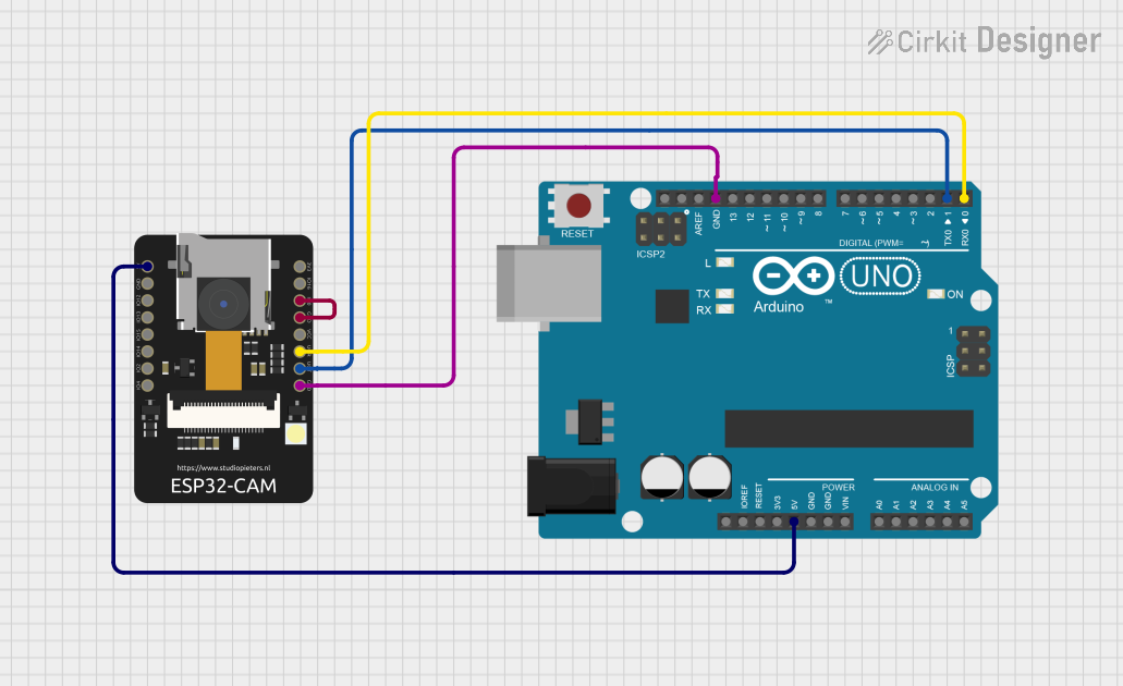
This circuit involves an Arduino UNO and an ESP32-CAM module. The Arduino UNO is responsible for receiving messages via UART communication, while the ESP32-CAM sends messages to the Arduino UNO. The two microcontrollers are interconnected to facilitate this communication.
Component List
Arduino UNO
- Description: A microcontroller board based on the ATmega328P.
- Pins: UNUSED, IOREF, Reset, 3.3V, 5V, GND, Vin, A0, A1, A2, A3, A4, A5, SCL, SDA, AREF, D13, D12, D11, D10, D9, D8, D7, D6, D5, D4, D3, D2, D1, D0
ESP32-CAM
- Description: A small-sized camera module with an ESP32-S chip.
- Pins: 5V, GND, IO12, IO13, IO15, IO14, IO2, IO4, VOT, VOR, VCC, IO0, IO16, 3V3
Wiring Details
Arduino UNO
- 5V: Connected to ESP32-CAM 5V
- GND: Connected to ESP32-CAM GND
- D1: Connected to ESP32-CAM VOT
- D0: Connected to ESP32-CAM VOR
ESP32-CAM
- 5V: Connected to Arduino UNO 5V
- GND: Connected to Arduino UNO GND and ESP32-CAM IO0
- VOT: Connected to Arduino UNO D1
- VOR: Connected to Arduino UNO D0
- IO0: Connected to ESP32-CAM GND
Code Documentation
Arduino UNO Code
void setup() {
  // Initialize Serial communication
  Serial.begin(9600); // Debugging
  Serial.println("Arduino UART Communication Initialized");
}

void loop() {
  // Check if data is available to read
  if (Serial.available() > 0) {
    // Read the incoming message
    String receivedMessage = Serial.readString();
    // Print the received message to Serial Monitor
    Serial.println("Message Received: " + receivedMessage);
  }
}
ESP32-CAM Code
#define RXp2 14  // RX pin for UART2
#define TXp2 15  // TX pin for UART2

void setup() {
  // Initialize Serial for debugging
  Serial.begin(115200);
  // Initialize UART2
  Serial2.begin(9600, SERIAL_8N1, RXp2, TXp2);
  Serial.println("ESP32 UART Communication Initialized");
}

void loop() {
  // Send a message to Arduino via Serial2
  String message = "Hello from ESP32";
  Serial2.println(message);

  // Print the sent message to Serial Monitor for debugging
  Serial.println("Message Sent: " + message);

  delay(1000); // Wait for 1 second before sending the next message
}
This documentation provides a comprehensive overview of the circuit, including the components used, their wiring details, and the code running on each microcontroller.