
Arduino UNO-Based IR Sensor Alarm with Buzzer and LED Indicator
View and Edit Project In Cirkit Designer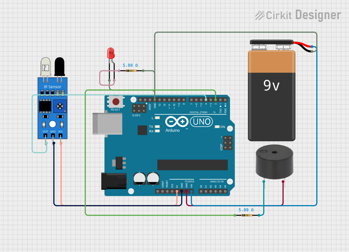
Circuit Documentation
Summary of the Circuit
This circuit is designed around an Arduino UNO microcontroller, which serves as the central processing unit. The circuit includes an infrared (IR) sensor for detecting objects or movements, a buzzer for audible alerts, an LED for visual indication, and a 9V battery to power the Arduino UNO. The circuit also incorporates resistors for current limiting purposes.
Component List
Arduino UNO
- Microcontroller board based on the ATmega328P
- It has 14 digital input/output pins, 6 analog inputs, a 16 MHz quartz crystal, a USB connection, a power jack, an ICSP header, and a reset button.
Buzzer
- An electromechanical component that produces sound
- Typically used for alarms or user feedback
IR Sensor
- A sensor that detects infrared light, often used in proximity or motion detection
9V Battery
- A standard 9-volt battery used to provide power to the circuit
LED: Two Pin (red)
- A red light-emitting diode used as an indicator light
Resistor (5 Ohms)
- A component that provides resistance in the circuit, used to limit current
Wiring Details
Arduino UNO
- 5V connected to the VCC of the IR sensor
- GND connected to:
- The GND of the IR sensor
- The GND of the buzzer
- The GND of the 9V battery
- The cathode of the LED through a resistor
- Vin connected to the positive terminal of the 9V battery
- D4 connected to the output of the IR sensor
- D2 connected to one end of a resistor
Buzzer
- PIN connected to the other end of a resistor
- GND connected to the GND of the Arduino UNO
IR Sensor
- VCC connected to the 5V of the Arduino UNO
- GND connected to the GND of the Arduino UNO
- OUT connected to the D4 of the Arduino UNO
9V Battery
- + connected to the Vin of the Arduino UNO
- - connected to the GND of the Arduino UNO
LED: Two Pin (red)
- Anode connected to one end of a resistor
- Cathode connected to the GND of the Arduino UNO
Resistor (5 Ohms)
- One resistor is connected between the D2 of the Arduino UNO and the PIN of the buzzer
- Another resistor is connected between the anode of the LED and the GND of the Arduino UNO
Documented Code
Arduino UNO Code (sketch.ino)
void setup() {
  // put your setup code here, to run once:

}

void loop() {
  // put your main code here, to run repeatedly:

}
Additional Notes (documentation.txt)
No additional code documentation was provided.