
Arduino UNO-Based Ultrasonic Distance Measurement with RGB Feedback and LCD Display
View and Edit Project In Cirkit Designer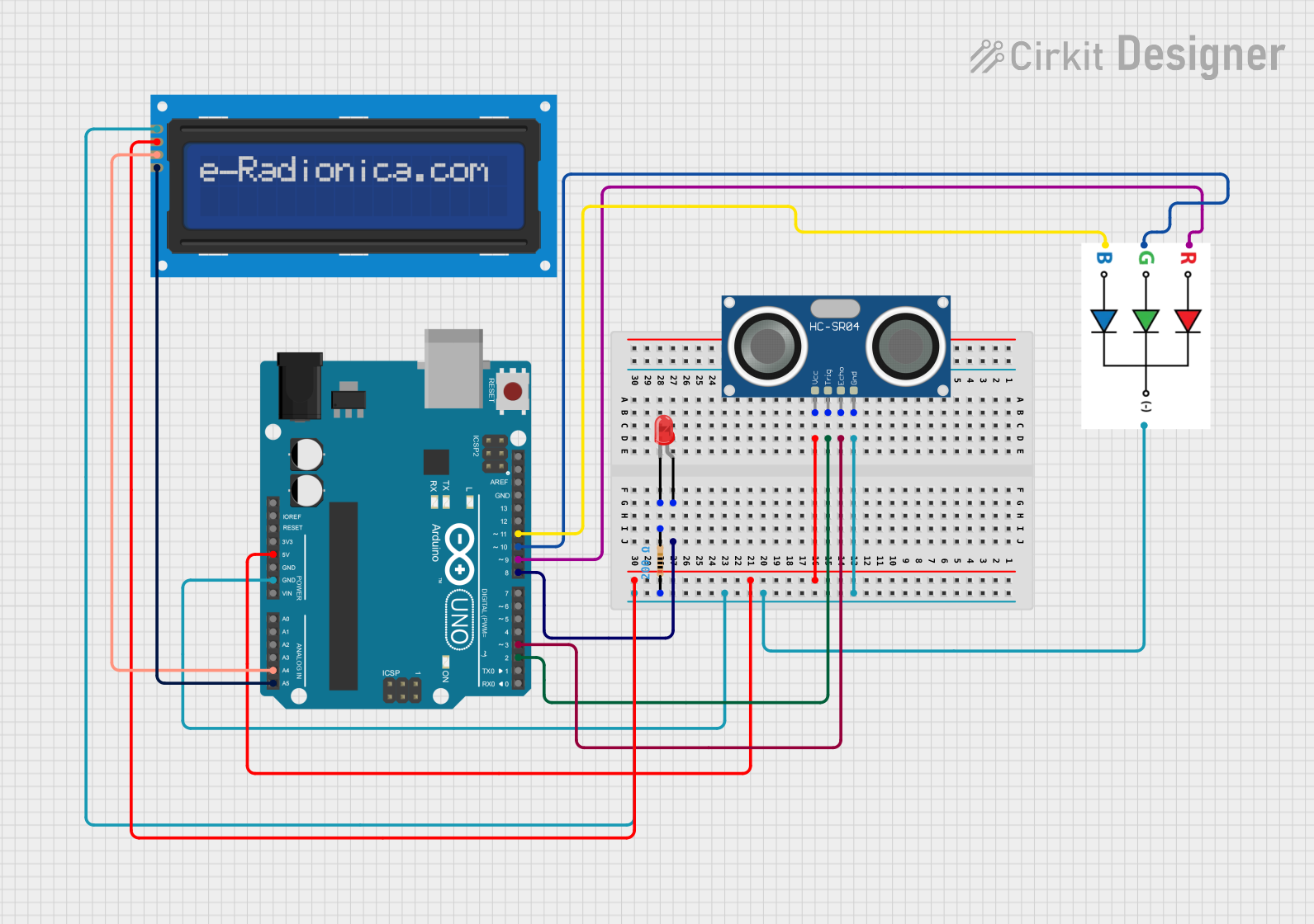
Circuit Documentation
Summary of the Circuit
This circuit is designed around an Arduino UNO microcontroller, which serves as the central processing unit. The circuit includes a variety of components such as an HC-SR04 Ultrasonic Sensor for distance measurement, an LED RGB for multi-color light emission, a two-pin red LED for indication purposes, a resistor to limit current to the red LED, and an LCD screen 16x2 with I2C interface for display purposes. The Arduino UNO controls these peripherals and communicates with the LCD screen via I2C protocol. Power distribution is managed from the Arduino's 5V and GND pins to the other components.
Component List
Arduino UNO
- Microcontroller board based on the ATmega328P
- It has 14 digital input/output pins, 6 analog inputs, a 16 MHz quartz crystal, a USB connection, a power jack, an ICSP header, and a reset button.
LED: Two Pin (red)
- A simple red light-emitting diode
- It has an anode and a cathode for standard diode connection.
Resistor
- A passive two-terminal electrical component that implements electrical resistance as a circuit element.
- Resistance: 200 Ohms
LED RGB
- A Red-Green-Blue multi-color LED
- It has four pins: one for each color (R, G, B) and a common cathode (-).
HC-SR04 Ultrasonic Sensor
- An ultrasonic distance sensor
- It has four pins: VCC for power, GND for ground, TRIG for triggering the distance measurement, and ECHO for receiving the distance signal.
LCD screen 16x2 I2C
- A 16x2 character LCD display with an I2C interface
- It has four pins: SCL and SDA for I2C communication, VCC for power, and GND for ground.
Wiring Details
Arduino UNO
- 5V to HC-SR04 VCC, LCD VCC
- GND to Resistor pin1, HC-SR04 GND, LED RGB -, LCD GND
- A4 to LCD SDA
- A5 to LCD SCL
- D11 to LED RGB B
- D10 to LED RGB G
- D9 to LED RGB R
- D8 to LED Two Pin (red) anode
- D3 to HC-SR04 ECHO
- D2 to HC-SR04 TRIG
LED: Two Pin (red)
- Anode connected to Arduino UNO D8
- Cathode connected to Resistor pin2
Resistor
- Pin1 connected to Arduino UNO GND
- Pin2 connected to LED (red) cathode
LED RGB
- R connected to Arduino UNO D9
- G connected to Arduino UNO D10
- B connected to Arduino UNO D11
-
- connected to Arduino UNO GND
HC-SR04 Ultrasonic Sensor
- VCC connected to Arduino UNO 5V
- TRIG connected to Arduino UNO D2
- ECHO connected to Arduino UNO D3
- GND connected to Arduino UNO GND
LCD screen 16x2 I2C
- SCL connected to Arduino UNO A5
- SDA connected to Arduino UNO A4
- VCC connected to Arduino UNO 5V
- GND connected to Arduino UNO GND
Documented Code
Arduino UNO Code (sketch.ino)
void setup() {
  // put your setup code here, to run once:

}

void loop() {
  // put your main code here, to run repeatedly:

}
Note: The provided code is a template and does not include specific functionality. It should be populated with the setup and loop functions to control the connected components as per the circuit's requirements.