Cirkit Designer
Your all-in-one circuit design IDE
Home /
Project Documentation
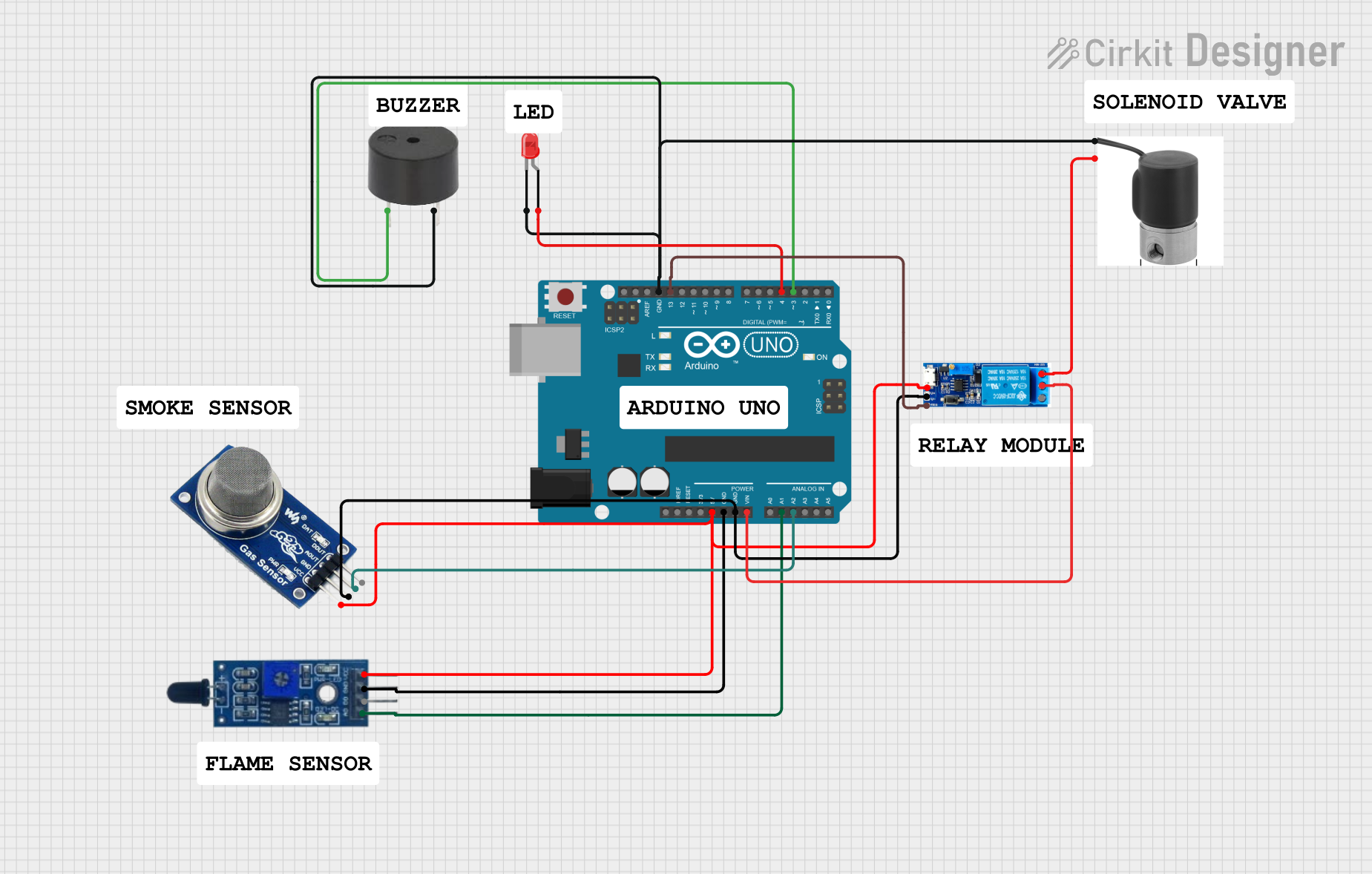
Arduino UNO-Based Fire and Gas Detection System with Alarm and Solenoid Valve Control
Circuit Documentation
Summary
This circuit is designed to detect flame and gas presence using a Flame Sensor and an MQ2 gas sensor. It also includes a buzzer and an LED for alerting purposes, and a solenoid valve controlled by a relay module. The entire system is managed by an Arduino UNO microcontroller.
Component List
Flame Sensor
- Pins: VCC, GND, D0, A0
- Description: Detects the presence of flame.
- Purpose in Circuit: Provides an analog signal indicating flame presence.
MQ2 Gas Sensor
- Pins: VCC, GND, AOUT, DOUT
- Description: Detects the presence of gases like LPG, smoke, alcohol, propane, hydrogen, methane, and carbon monoxide.
- Purpose in Circuit: Provides an analog signal indicating gas presence.
Buzzer
- Pins: PIN, GND
- Description: Emits sound when activated.
- Purpose in Circuit: Alerts when flame or gas is detected.
LED: Two Pin (red)
- Pins: Cathode, Anode
- Description: Emits light when activated.
- Purpose in Circuit: Visual alert when flame or gas is detected.
Arduino UNO
- Pins: UNUSED, IOREF, Reset, 3.3V, 5V, GND, Vin, A0, A1, A2, A3, A4, A5, SCL, SDA, AREF, D13, D12, D11, D10, D9, D8, D7, D6, D5, D4, D3, D2, D1, D0
- Description: Microcontroller board based on the ATmega328P.
- Purpose in Circuit: Controls the entire system, reads sensor data, and activates the buzzer, LED, and solenoid valve.
Solenoid Valve 12V
- Pins: GND, 12V
- Description: Controls the flow of liquid or gas.
- Purpose in Circuit: Activated to control the flow when flame or gas is detected.
Relay Module 5V-30V
- Pins: Common Contact, Normally Open, Normally Closed, Trigger, V-, V+
- Description: Electrically operated switch.
- Purpose in Circuit: Controls the solenoid valve based on signals from the Arduino.
Wiring Details
Flame Sensor
- VCC connected to 5V on Arduino UNO.
- GND connected to GND on Arduino UNO.
- A0 connected to A1 on Arduino UNO.
MQ2 Gas Sensor
- VCC connected to 5V on Arduino UNO.
- GND connected to GND on Arduino UNO.
- AOUT connected to A2 on Arduino UNO.
Buzzer
- PIN connected to D3 on Arduino UNO.
- GND connected to GND on Arduino UNO.
LED: Two Pin (red)
- Anode connected to D4 on Arduino UNO.
- Cathode connected to GND on Arduino UNO.
Arduino UNO
- 5V connected to VCC on Flame Sensor and MQ2 Gas Sensor.
- GND connected to GND on Flame Sensor, MQ2 Gas Sensor, Buzzer, LED, and Solenoid Valve.
- A1 connected to A0 on Flame Sensor.
- A2 connected to AOUT on MQ2 Gas Sensor.
- D3 connected to PIN on Buzzer.
- D4 connected to Anode on LED.
- D13 connected to Trigger on Relay Module.
- Vin connected to Common Contact on Relay Module.
Solenoid Valve 12V
- GND connected to GND on Arduino UNO.
- 12V connected to Normally Closed on Relay Module.
Relay Module 5V-30V
- V+ connected to 5V on Arduino UNO.
- V- connected to GND on Arduino UNO.
- Common Contact connected to Vin on Arduino UNO.
- Trigger connected to D13 on Arduino UNO.
- Normally Closed connected to 12V on Solenoid Valve.
Code Documentation
Arduino UNO Code
void setup() {
  // Initialize serial communication at 9600 bits per second:
  Serial.begin(9600);

  // Set up the analog pins for input:
  pinMode(A0, INPUT);
  pinMode(A1, INPUT);
  pinMode(A2, INPUT);
}

void loop() {
  // Read the input on analog pins A0, A1, and A2:
  int sensorValue0 = analogRead(A0);
  int sensorValue1 = analogRead(A1);
  int sensorValue2 = analogRead(A2);

  // Print out the values you read:
  Serial.print("Sensor 0: ");
  Serial.println(sensorValue0);
  Serial.print("Sensor 1: ");
  Serial.println(sensorValue1);
  Serial.print("Sensor 2: ");
  Serial.println(sensorValue2);

  // Delay a bit for stability:
  delay(1000);
}
This code initializes the serial communication and sets up the analog pins A0, A1, and A2 for input. It reads the sensor values from these pins and prints them to the serial monitor every second.