
Circuit Documentation
Summary of the Circuit
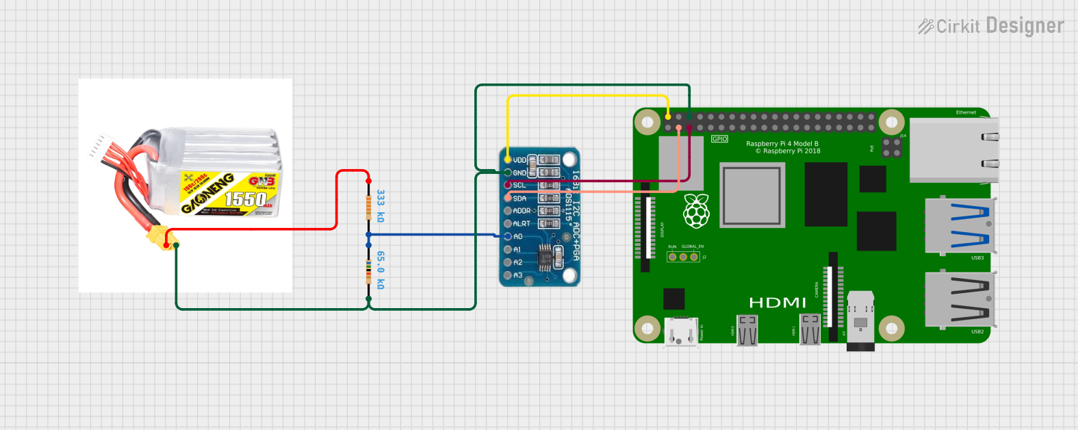
This circuit is designed to interface an ADS1115 analog-to-digital converter (ADC) with a Raspberry Pi 4B microcontroller. The ADS1115 is used to measure the voltage of a 5s lipo battery through a voltage divider composed of two resistors. The Raspberry Pi reads the ADC values via I2C communication and calculates the battery's voltage and percentage charge. The circuit is powered by the 5V supply from the Raspberry Pi, and the ground is shared across all components.
Component List
ADS1115
- Description: 16-bit ADC with I2C interface.
- Purpose: To convert analog signals from the battery voltage divider into digital values for the Raspberry Pi to process.
Resistor 1
- Resistance: 65,000 Ohms (65kΩ)
- Purpose: Part of the voltage divider to step down the battery voltage to a safe level for the ADC.
Resistor 2
- Resistance: 333,000 Ohms (333kΩ)
- Purpose: Part of the voltage divider to step down the battery voltage to a safe level for the ADC.
Raspberry Pi 4B
- Description: A powerful microcontroller with multiple GPIO pins and I2C communication capabilities.
- Purpose: To read data from the ADS1115 ADC and calculate the battery's voltage and percentage charge.
5s Lipo Battery
- Description: A rechargeable battery with a high energy density.
- Purpose: To provide power to the circuit and be the subject of voltage monitoring.
Wiring Details
ADS1115
- VDD: Connected to Raspberry Pi 4B 5V.
- GND: Connected to Raspberry Pi 4B GND, Resistor 1 pin 2, and 5s lipo battery -ve.
- SCL: Connected to Raspberry Pi 4B GPIO3.
- SDA: Connected to Raspberry Pi 4B GPIO2.
- A0: Connected to Resistor 1 pin 1 and Resistor 2 pin 2.
Resistor 1 (65kΩ)
- Pin 1: Connected to ADS1115 A0.
- Pin 2: Connected to ADS1115 GND.
Resistor 2 (333kΩ)
- Pin 1: Connected to 5s lipo battery +ve.
- Pin 2: Connected to ADS1115 A0.
Raspberry Pi 4B
- 5V: Connected to ADS1115 VDD.
- GND: Connected to ADS1115 GND.
- GPIO3: Connected to ADS1115 SCL.
- GPIO2: Connected to ADS1115 SDA.
5s Lipo Battery
- +ve: Connected to Resistor 2 pin 1.
- -ve: Connected to ADS1115 GND.
Documented Code
Raspberry Pi 4B Code (Python)
import time
import board
import busio
import adafruit_ads1x15.ads1115 as ADS

i2c = busio.I2C(board.SCL,board.SDA)

ads = ADS.ADS1115(i2c,address=0x48)
R2 = 66000.0
R1 = 331000.0

min_adcBatteryVoltage=15.0
max_adcBatteryVoltage=21.0
max_adc_adc_voltage=4.096
max_adc_adc_value=32767

def readbattery():
    try:
        adc_value=ads.read(0)
        print(adc_value)
        adc_value=adc_value+9000
        if adc_value==0 or adc_value==32767:
            return None,None,True

        measured_voltage=adc_value*(max_adc_adc_voltage/max_adc_adc_value)
        voltage=measured_voltage*((R1+R2)/R2)

        battery_percentage = ((voltage - min_adcBatteryVoltage) / (max_adcBatteryVoltage - min_adcBatteryVoltage)) * 100.0
        battery_percentage = max(0, min(battery_percentage, 100))

        return voltage,battery_percentage,False
    except Exception as e:
        print(f"Error reading battery status:{e}")
        return 'check connections'

def getbatterystatus():
    while True:
        battery_voltage=None
        battery_percentage=None
        error=True

        max_adc_attempts=5
        attempts=0
        success=False

        while attempts<max_adc_attempts and not success:
            battery_voltage,battery_percentage,error=readbattery()

            if not error:
                success=True

                print(f"Battery Voltage:{battery_voltage:.2f}V")
                print(f"Battery Percentage:{battery_percentage:.2f}%")

                if battery_percentage<20.0:
                    print("Warning: Battery level is below 20%")
                    return 0
                elif battery_percentage<50 and battery_percentage>20:
                    print('battry less than 50%')
                    return 1
                else:
                    print('good to go')
                    return 2
            else:

                attempts+=1
                if attempts<max_adc_attempts:
                    time.sleep(3)
                break

        if not success:

            print("Error: Unable to read battery status. Please check the connection.")

        time.sleep(5)

def get_battery_percentage():
    battery_voltage,battery_percentage,error=readbattery()
    if not error:
        return battery_percentage
    else:
        return error
ADS1115 Code (Arduino)
void setup() {
  // put your setup code here, to run once:

}

void loop() {
  // put your main code here, to run repeatedly:

}
Note: The Arduino code provided for the ADS1115 is empty and does not include any functionality. It is likely that the ADS1115 is being used with its default settings and controlled directly by the Raspberry Pi via I2C, hence no additional Arduino code is necessary.