Cirkit Designer
Your all-in-one circuit design IDE
Home /
Project Documentation
Arduino UNO Controlled Bipolar Stepper Motor with Keypad Interface
Circuit Documentation
Summary
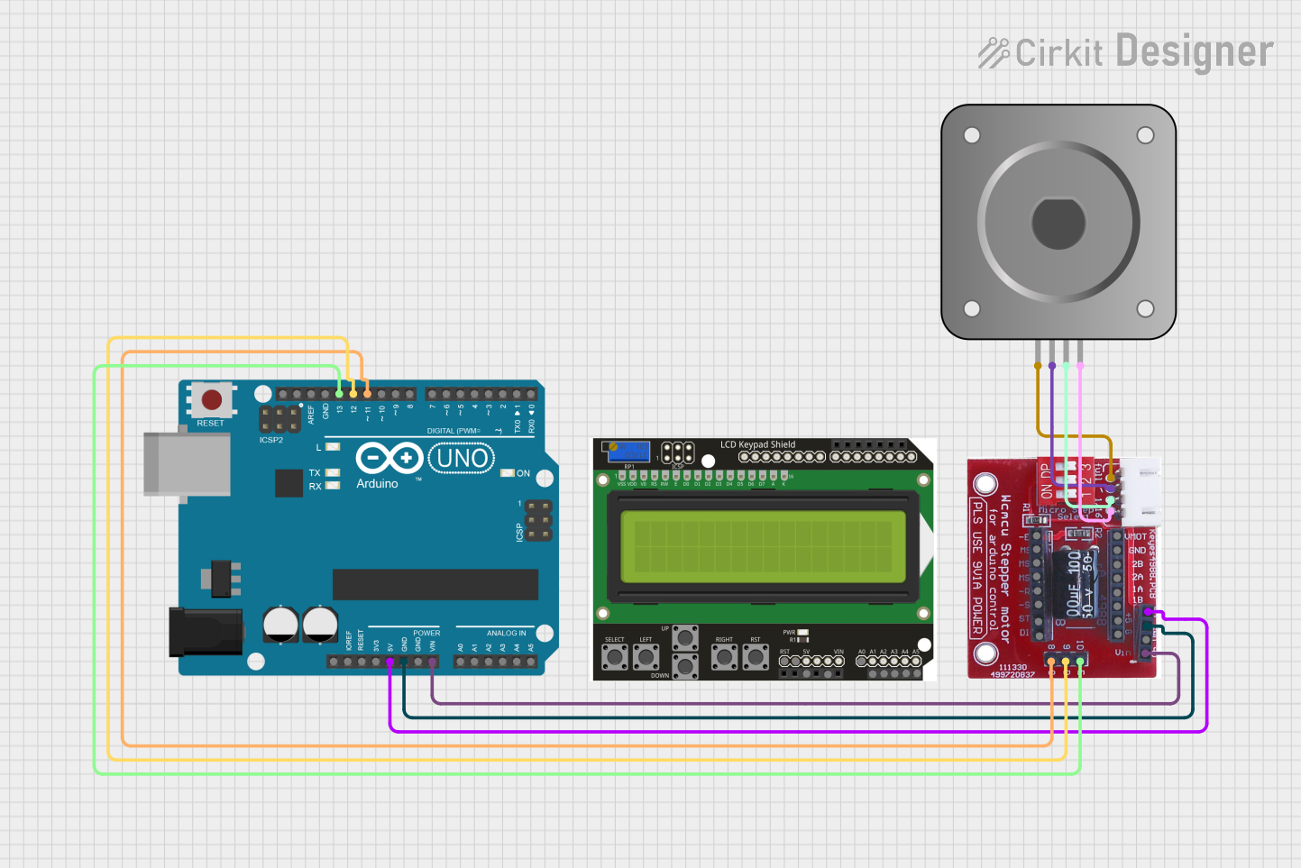
This circuit is designed to control a bipolar stepper motor using an Arduino UNO and a DRV8825 stepper motor driver. The circuit also includes a keypad shield for user input. The Arduino UNO serves as the main controller, interfacing with the stepper motor driver to control the stepper motor's movements.
Component List
Bipolar Stepper Motor (NEMA 17)
- Pins: A-, A+, B+, B-
- Description: A bipolar stepper motor used for precise control of rotational movements.
- Purpose in Circuit: Provides mechanical movement.
Keypad Shield
- Pins: rst, d, 5v, vin, A0, A1, A2, A3, A4, A5
- Description: A shield that provides a keypad interface for user input.
- Purpose in Circuit: Allows user interaction and input.
DRV8825
- Pins: EN, M0, M1, M2, RST, SLP, STEP, DIR, VMOT, GND MOTOR, B2, B1, A1, A2, FAULT, GND LOGIC
- Description: A stepper motor driver used to control the bipolar stepper motor.
- Purpose in Circuit: Drives the stepper motor based on control signals from the Arduino.
A4988/DRV8825 Stepper Motor Drive Control Board/Expansion Board
- Pins: Enabler, Direction, Step, V in Motor, GND Motor and Logic, Microstep 1, Microstep 2, Microstep 3, Reset, Sleep, GND Logic, Fault, 1B, 1A, 2A, 2B, GND Motor, V Motor, 5V Fault Supply
- Description: An expansion board for the DRV8825 stepper motor driver.
- Purpose in Circuit: Provides additional interfacing and control options for the stepper motor driver.
Arduino UNO
- Pins: UNUSED, IOREF, Reset, 3.3V, 5V, GND, Vin, A0, A1, A2, A3, A4, A5, SCL, SDA, AREF, D13, D12, D11, D10, D9, D8, D7, D6, D5, D4, D3, D2, D1, D0
- Description: A microcontroller board based on the ATmega328P.
- Purpose in Circuit: Acts as the main controller for the circuit, interfacing with the stepper motor driver and keypad shield.
Wiring Details
Bipolar Stepper Motor (NEMA 17)
- A- connected to 1B on A4988/DRV8825 Stepper Motor Drive Control Board/Expansion Board
- A+ connected to 1A on A4988/DRV8825 Stepper Motor Drive Control Board/Expansion Board
- B+ connected to 2A on A4988/DRV8825 Stepper Motor Drive Control Board/Expansion Board
- B- connected to 2B on A4988/DRV8825 Stepper Motor Drive Control Board/Expansion Board
Keypad Shield
- No connections specified in the provided net list.
DRV8825
- No direct connections specified in the provided net list.
A4988/DRV8825 Stepper Motor Drive Control Board/Expansion Board
- 5V Fault Supply connected to 5V on Arduino UNO
- GND Motor and Logic connected to GND on Arduino UNO
- V in Motor connected to Vin on Arduino UNO
- Enabler connected to D13 on Arduino UNO
- Direction connected to D12 on Arduino UNO
- Step connected to D11 on Arduino UNO
Arduino UNO
- 5V connected to 5V Fault Supply on A4988/DRV8825 Stepper Motor Drive Control Board/Expansion Board
- GND connected to GND Motor and Logic on A4988/DRV8825 Stepper Motor Drive Control Board/Expansion Board
- Vin connected to V in Motor on A4988/DRV8825 Stepper Motor Drive Control Board/Expansion Board
- D13 connected to Enabler on A4988/DRV8825 Stepper Motor Drive Control Board/Expansion Board
- D12 connected to Direction on A4988/DRV8825 Stepper Motor Drive Control Board/Expansion Board
- D11 connected to Step on A4988/DRV8825 Stepper Motor Drive Control Board/Expansion Board
Documented Code
Arduino UNO Code (sketch.ino)
void setup() {
  // put your setup code here, to run once:

}

void loop() {
  // put your main code here, to run repeatedly:

}
Additional Documentation (documentation.txt)
This documentation provides a comprehensive overview of the circuit, including a summary, detailed component list, wiring details, and documented code.