
Circuit Documentation
Summary
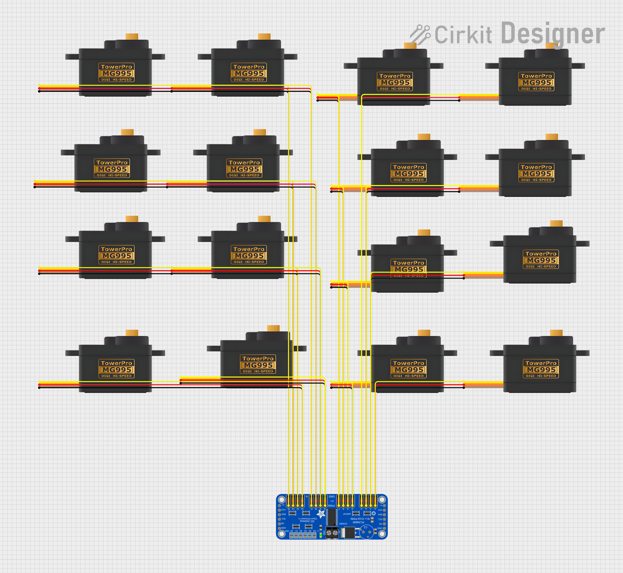
This circuit is designed to control multiple servomotors using the Adafruit PCA9685 PWM Servo Breakout board. The PCA9685 board is capable of driving up to 16 servomotors with individual PWM signals, allowing for precise control of each motor's position. The servomotors are powered by a common 5V supply and share a ground connection with the PCA9685 board.
Component List
Adafruit PCA9685 PWM Servo Breakout
- Description: A 16-channel, 12-bit PWM Fm+ I2C-bus LED controller.
- Purpose: To generate PWM signals for controlling multiple servomotors.
- Pins:
- 5.0V
- GND
- PWRIN
- SDA
- SCL
- OE
- PWM0 to PWM15 (16 PWM output pins)
Servomotor MG995
- Description: A high-torque digital servomotor.
- Purpose: To perform mechanical actions as instructed by the PWM signals.
- Pins:
- SIG (Signal)
- VCC (Power)
- GND (Ground)
Wiring Details
Adafruit PCA9685 PWM Servo Breakout
- 5.0V: Connected to the VCC pin of all servomotors.
- GND: Connected to the GND pin of all servomotors.
- PWM0 to PWM15: Each PWM output is connected to the SIG pin of a corresponding servomotor.
Servomotor MG995
- SIG: Connected to a unique PWM output on the PCA9685 board.
- VCC: Connected to the 5.0V pin on the PCA9685 board.
- GND: Connected to the GND pin on the PCA9685 board.
Documented Code
There is no embedded code provided for the microcontrollers in this circuit. The operation of the circuit is dependent on external control signals, likely provided by a separate microcontroller or computer interfacing with the PCA9685 board via the I2C bus. The user must implement the code to generate the appropriate PWM signals for the servomotors using the PCA9685's I2C interface.