
ESP32-Based Smart Lighting System with Ambient Light Sensing and IR Remote Control
View and Edit Project In Cirkit Designer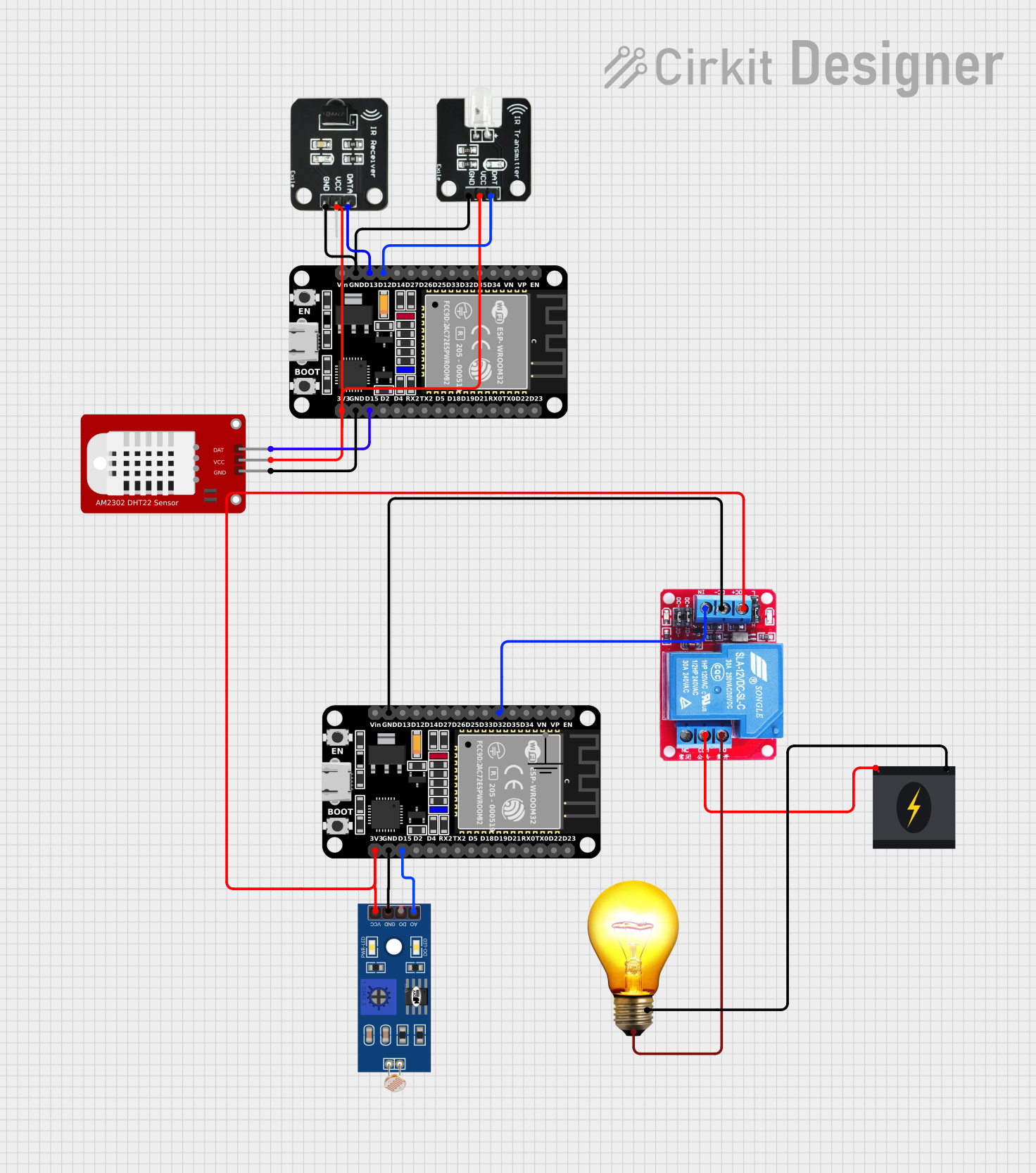
Circuit Documentation
Summary
The circuit in question appears to be a smart control system designed to interface with various sensors and actuators. It includes two ESP32 microcontrollers, which are likely used for processing and communication purposes. The circuit can control an AC bulb via a 12v relay, which is triggered by one of the ESP32s. It also includes an LDR (Light Dependent Resistor) for light sensing, an IR transmitter and receiver for infrared communication, and a DHT22 sensor for measuring temperature and humidity. The power for the relay's coil is derived from the 3.3V supply of the ESP32, and the AC bulb is powered by a 240v power source.
Component List
ESP32 (30 pin)
- A microcontroller with WiFi and Bluetooth capabilities, featuring a variety of digital and analog pins.
12v Relay
- An electromechanical switch that allows the ESP32 to control high-power devices such as the AC bulb.
LDR (Light Dependent Resistor)
- A sensor that changes resistance based on the ambient light level.
GND (Ground)
- A common reference point for the electrical current in the circuit.
240v Power Source
- Provides the main power for the AC bulb.
AC Bulb
- A standard bulb that operates on 240v AC power.
IR Transmitter
- An infrared LED that can be used to send signals to other infrared-enabled devices.
DHT22
- A sensor used for measuring ambient temperature and humidity.
IR Receiver
- A module that can detect infrared signals from a remote control or transmitter.
Wiring Details
ESP32 (30 pin)
D32connected to theINpin of the 12v Relay.GNDconnected to theGNDpin of the 12v Relay and theGNDpin of the LDR.3V3connected to theDC+pin of the 12v Relay and theVCCpin of the LDR.D15connected to theA0pin of the LDR.D12connected to theDATpin of the IR Transmitter.D13connected to theDATApin of the IR Receiver.GNDconnected to theGNDpins of the IR Transmitter and IR Receiver.3V3connected to theVCCpins of the IR Transmitter, IR Receiver, and DHT22.D15connected to theDATpin of the DHT22.
12v Relay
INconnected toD32on the ESP32.DC-connected toGNDon the ESP32.DC+connected to3V3on the ESP32.NO(Normally Open) connected to theP(Positive) pin of the AC Bulb.COM(Common) connected to theLivewire of the 240v Power Source.
LDR
A0connected toD15on the ESP32.GNDconnected toGNDon the ESP32.VCCconnected to3V3on the ESP32.
AC Bulb
Pconnected to theNOpin of the 12v Relay.N(Neutral) connected to theNeutralwire of the 240v Power Source.
IR Transmitter
DATconnected toD12on the ESP32.VCCconnected to3V3on the ESP32.GNDconnected toGNDon the ESP32.
DHT22
DATconnected toD15on the ESP32.VCCconnected to3V3on the ESP32.GNDconnected toGNDon the ESP32.
IR Receiver
DATAconnected toD13on the ESP32.VCCconnected to3V3on the ESP32.GNDconnected toGNDon the ESP32.
Documented Code
No code was provided for the microcontrollers in the circuit. For this system to function, code would need to be written and uploaded to the ESP32 microcontrollers to handle input from the LDR and DHT22 sensors, control the relay to power the AC bulb, and manage IR communication with the IR transmitter and receiver. The code would likely include routines for reading sensor values, debounce logic for stable relay operation, and protocols for IR signal encoding and decoding.