Arduino UNO RFID Door Lock System with Relay and Buzzer Notification
Circuit Documentation
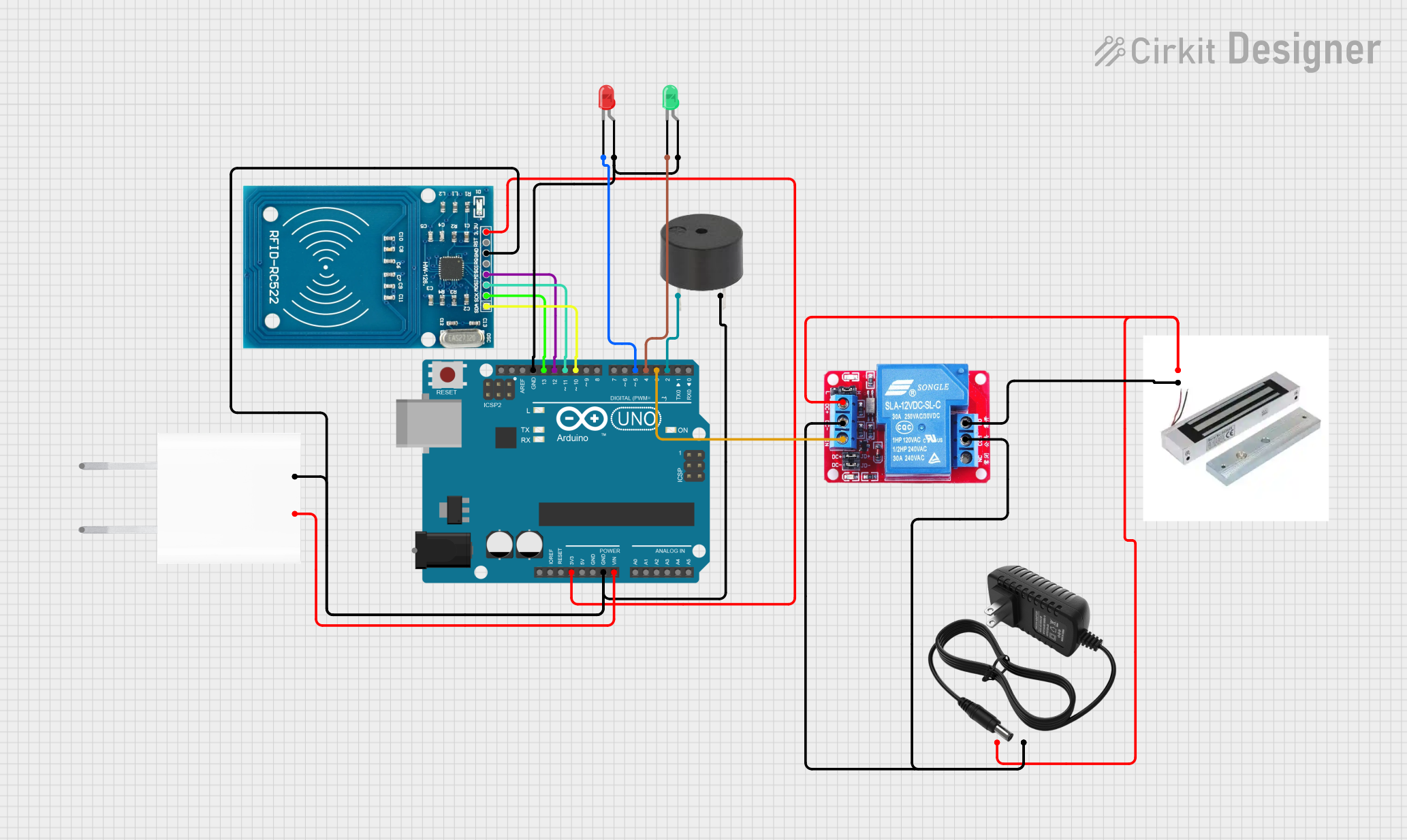
Summary of the Circuit
This circuit is designed to control a door lock system using RFID technology. It features an Arduino UNO microcontroller interfaced with an RFID-RC522 module to read RFID tags. The system unlocks a magnetic lock if an authorized RFID tag is presented. Visual feedback is provided through a green LED for access granted and a red LED for access denied. An audible alert is given by a buzzer, with different tones indicating accepted or rejected tags. The circuit is powered by a 5V adapter, and a 12V power supply is used to control the magnetic lock through a 12V relay.
Component List
Arduino UNO
- Microcontroller board based on the ATmega328P
- Used as the main controller for the RFID door lock system
RFID-RC522
- RFID reader/writer module
- Operates at 13.56 MHz for reading RFID tags
LED: Two Pin (green)
- Visual indicator for access granted
- Lights up when an authorized RFID tag is detected
LED: Two Pin (red)
- Visual indicator for access denied
- Lights up when an unauthorized RFID tag is detected
Buzzer
- Audible indicator for access granted or denied
- Sounds with different tones based on the RFID tag status
5V Adapter
- Power supply for the Arduino UNO and RFID-RC522
- Converts AC to 5V DC
Magnetic Lock
- Electromagnetic locking mechanism
- Secures the door and is controlled by the relay
12V Relay
- Electromechanical switch
- Used to control the high-power circuit of the magnetic lock with the Arduino's low-power signal
12V Power Supply
- Provides power to the magnetic lock through the relay
- Supplies 12V DC
Wiring Details
Arduino UNO
3.3Vconnected to RFID-RC522 VCC (3.3V)GNDconnected to common ground netVinconnected to 5V Adapter 5V outputD13connected to RFID-RC522 SCKD12connected to RFID-RC522 MISOD11connected to RFID-RC522 MOSID10connected to RFID-RC522 SDAD5connected to red LED cathodeD4connected to green LED cathodeD3connected to 12V Relay IND2connected to buzzer PIN
RFID-RC522
VCC (3.3V)connected to Arduino UNO 3.3VGNDconnected to common ground netSCKconnected to Arduino UNO D13MISOconnected to Arduino UNO D12MOSIconnected to Arduino UNO D11SDAconnected to Arduino UNO D10
LED: Two Pin (green)
anodeconnected to common ground netcathodeconnected to Arduino UNO D4
LED: Two Pin (red)
anodeconnected to common ground netcathodeconnected to Arduino UNO D5
Buzzer
PINconnected to Arduino UNO D2GNDconnected to common ground net
5V Adapter
5Vconnected to Arduino UNO VinGNDconnected to common ground net
Magnetic Lock
Sconnected to 12V Relay DC+GNDconnected to 12V Relay NO
12V Relay
INconnected to Arduino UNO D3DC+connected to Magnetic Lock S and 12V Power Supply +DC-connected to 12V Power Supply -NOconnected to Magnetic Lock GND
12V Power Supply
+connected to 12V Relay DC+-connected to 12V Relay DC-
Documented Code
/*
 * This Arduino Sketch controls a door lock system using RFID.
 * The system reads RFID tags and unlocks the door if the tag is authorized.
 * A buzzer sounds differently for accepted and rejected tags.
 * Two example RFID tags are used for access control.
 */

#include <SPI.h>
#include <MFRC522.h>

#define RST_PIN 9
#define SS_PIN 10
#define RED_LED_PIN 5
#define GREEN_LED_PIN 4
#define RELAY_PIN 3
#define BUZZER_PIN 2

MFRC522 mfrc522(SS_PIN, RST_PIN);

// Example authorized RFID tag UIDs
byte authorizedUID1[] = {0xDE, 0xAD, 0xBE, 0xEF};
byte authorizedUID2[] = {0xCA, 0xFE, 0xBA, 0xBE};

void setup() {
  Serial.begin(9600);
  SPI.begin();
  mfrc522.PCD_Init();
  pinMode(RED_LED_PIN, OUTPUT);
  pinMode(GREEN_LED_PIN, OUTPUT);
  pinMode(RELAY_PIN, OUTPUT);
  pinMode(BUZZER_PIN, OUTPUT);
  digitalWrite(RELAY_PIN, LOW); // Ensure the relay is off initially
}

void loop() {
  if (!mfrc522.PICC_IsNewCardPresent() || !mfrc522.PICC_ReadCardSerial()) {
    return;
  }

  if (isAuthorized(mfrc522.uid.uidByte, mfrc522.uid.size)) {
    grantAccess();
  } else {
    denyAccess();
  }

  mfrc522.PICC_HaltA();
}

bool isAuthorized(byte *uid, byte uidSize) {
  if (uidSize != 4) return false;
  if (memcmp(uid, authorizedUID1, 4) == 0) return true;
  if (memcmp(uid, authorizedUID2, 4) == 0) return true;
  return false;
}

void grantAccess() {
  digitalWrite(GREEN_LED_PIN, HIGH);
  digitalWrite(RED_LED_PIN, LOW);
  digitalWrite(RELAY_PIN, HIGH);
  tone(BUZZER_PIN, 1000, 200); // Short beep for accepted tag
  delay(5000); // Keep the door unlocked for 5 seconds
  digitalWrite(RELAY_PIN, LOW);
  digitalWrite(GREEN_LED_PIN, LOW);
}

void denyAccess() {
  digitalWrite(RED_LED_PIN, HIGH);
  digitalWrite(GREEN_LED_PIN, LOW);
  tone(BUZZER_PIN, 500, 1000); // Long beep for rejected tag
  delay(1000);
  digitalWrite(RED_LED_PIN, LOW);
}
This code is responsible for initializing the RFID reader and setting up the pins for the LEDs, relay, and buzzer. It continuously checks for new RFID cards, compares the UID of the card with authorized UIDs, and then either grants or denies access accordingly. The relay is activated to unlock the door for authorized access, and the LEDs and buzzer provide the corresponding visual and audible feedback.