Cirkit Designer
Your all-in-one circuit design IDE
Home /
Project Documentation
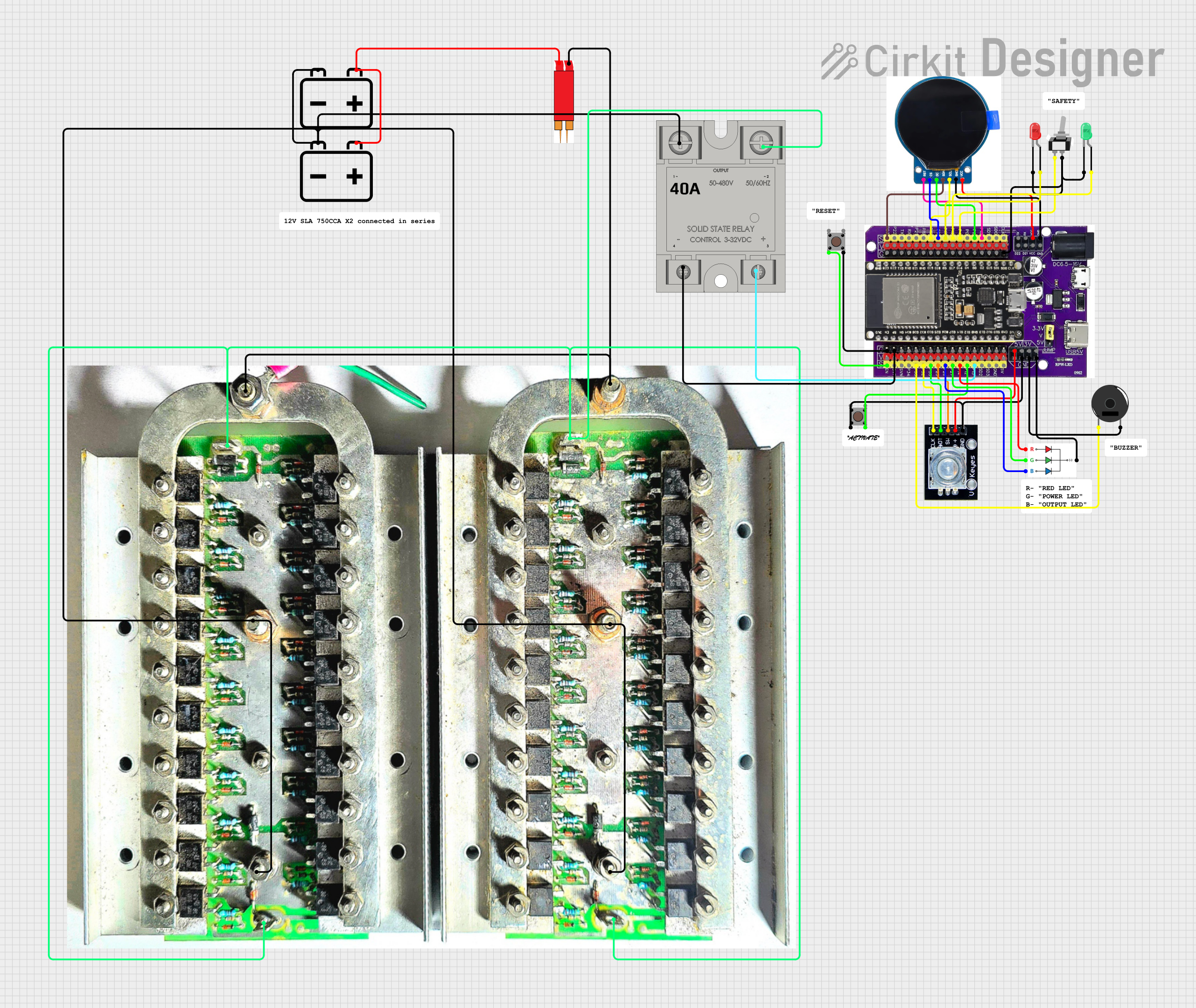
ESP32-Based Battery Welding Station with TFT Display and Rotary Encoder
Circuit Documentation
Summary
This circuit is designed to control a welding pen using an ESP32 microcontroller. It includes a rotary encoder for user input, a TFT display for visual feedback, LEDs for status indication, a piezo buzzer for audio feedback, and a solid-state relay (SSR) for controlling high-power devices. The circuit also includes a toggle switch and pushbuttons for additional user controls.
Component List
Esp32 on Baseboard
- Description: Microcontroller used for controlling the circuit.
- Pins: GPIO23, GPIO22, GPIO1/TX, GPIO3/RX, GPIO21, GPIO19, GPIO18, GPIO5, GPIO17, GPIO16, GPIO4, GPIO0, GPIO2, GPIO15, SD1, SD0, CLK, V, G, GPIO36, GPIO39, GPIO34, GPIO35, GPIO32, GPIO33, GPIO25, GPIO26, GPIO27, GPIO14, GPIO12, GPIO13, SD2, SD3, GND, 5V, 3V, TX, RX, VCC, D22, D21
Rotary Encoder
- Description: Used for user input to adjust settings.
- Pins: clk, dt, sw, gnd, +
Round TFT Display
- Description: Provides visual feedback to the user.
- Pins: RST, CS, DC, SDA, SCL, GND, VCC
Pushbutton
- Description: Used for user input.
- Pins: Pin 3 (out), Pin 4 (out), Pin 1 (in), Pin 2 (in)
12v Battery
- Description: Power source for the circuit.
- Pins: -, +
MOSFET Bank of 40xIRF540N
- Description: Used for switching high-power loads.
- Pins: Drain A, Drain B, Source A1, Source A2, Gate A1, Gate A2, Gate B1, Gate B2, Source B1, Source B2
18650 Battery Welding Pen
- Description: The welding pen controlled by the circuit.
- Pins: + INPUT, - INPUT
SSR-40A
- Description: Solid-state relay for controlling high-power devices.
- Pins: -, +, Lin, Lout
RGB LED
- Description: Provides visual status indication.
- Pins: B, G, R, GND
Piezo Buzzer
- Description: Provides audio feedback.
- Pins: pin 1, pin 2
Toggle Switch SPST
- Description: Used for toggling the ready state.
- Pins: L1, COM
LED: Two Pin (green)
- Description: Provides visual status indication.
- Pins: cathode, anode
LED: Two Pin (red)
- Description: Provides visual status indication.
- Pins: cathode, anode
Wiring Details
Esp32 on Baseboard
- GPIO23: Connected to SDA pin of the Round TFT Display
- GPIO18: Connected to SCL pin of the Round TFT Display
- GPIO5: Connected to CS pin of the Round TFT Display
- GPIO17: Connected to anode pin of the LED: Two Pin (red)
- GPIO16: Connected to anode pin of the LED: Two Pin (green)
- GPIO4: Connected to L1 pin of the Toggle Switch SPST
- GPIO2: Connected to DC pin of the Round TFT Display
- GPIO15: Connected to RST pin of the Round TFT Display
- G: Connected to cathode pin of the LED: Two Pin (red), cathode pin of the LED: Two Pin (green), COM pin of the Toggle Switch SPST, Pin 4 (out) of the Pushbutton, - pin of the SSR-40A
- GPIO35: Connected to pin 1 of the Piezo Buzzer
- GPIO32: Connected to clk pin of the Rotary Encoder
- GPIO33: Connected to dt pin of the Rotary Encoder
- GPIO25: Connected to sw pin of the Rotary Encoder
- GPIO26: Connected to B pin of the RGB LED
- GPIO27: Connected to G pin of the RGB LED
- GPIO14: Connected to R pin of the RGB LED
- GPIO12: Connected to Pin 4 (out) of the Pushbutton
- GPIO13: Connected to + pin of the SSR-40A
- GND: Connected to gnd pin of the Rotary Encoder, pin 2 of the Piezo Buzzer, GND pin of the RGB LED, GND pin of the Round TFT Display
- 5V: Connected to + pin of the Rotary Encoder
- VCC: Connected to VCC pin of the Round TFT Display
Rotary Encoder
- clk: Connected to GPIO32 pin of the Esp32 on Baseboard
- dt: Connected to GPIO33 pin of the Esp32 on Baseboard
- sw: Connected to GPIO25 pin of the Esp32 on Baseboard
- gnd: Connected to GND pin of the Esp32 on Baseboard
- +: Connected to 5V pin of the Esp32 on Baseboard
Round TFT Display
- SDA: Connected to GPIO23 pin of the Esp32 on Baseboard
- SCL: Connected to GPIO18 pin of the Esp32 on Baseboard
- CS: Connected to GPIO5 pin of the Esp32 on Baseboard
- DC: Connected to GPIO2 pin of the Esp32 on Baseboard
- RST: Connected to GPIO15 pin of the Esp32 on Baseboard
- GND: Connected to GND pin of the Esp32 on Baseboard
- VCC: Connected to VCC pin of the Esp32 on Baseboard
Pushbutton
- Pin 2 (in): Connected to GPIO12 pin of the Esp32 on Baseboard
- Pin 4 (out): Connected to G pin of the Esp32 on Baseboard
12v Battery
- -: Connected to Lin pin of the SSR-40A
- +: Connected to + INPUT pin of the 18650 Battery Welding Pen
MOSFET Bank of 40xIRF540N
- Source A1: Connected to Source A2, Source B1, Source B2
- Drain A: Connected to Drain B, - INPUT pin of the 18650 Battery Welding Pen
- Gate A1: Connected to Gate A2, Gate B1, Gate B2
18650 Battery Welding Pen
- + INPUT: Connected to + pin of the 12v Battery
- - INPUT: Connected to Drain A pin of the MOSFET Bank of 40xIRF540N
SSR-40A
- -: Connected to G pin of the Esp32 on Baseboard
- +: Connected to GPIO13 pin of the Esp32 on Baseboard
- Lin: Connected to - pin of the 12v Battery
- Lout: Connected to Gate A1 pin of the MOSFET Bank of 40xIRF540N
RGB LED
- B: Connected to GPIO26 pin of the Esp32 on Baseboard
- G: Connected to GPIO27 pin of the Esp32 on Baseboard
- R: Connected to GPIO14 pin of the Esp32 on Baseboard
- GND: Connected to GND pin of the Esp32 on Baseboard
Piezo Buzzer
- pin 1: Connected to GPIO35 pin of the Esp32 on Baseboard
- pin 2: Connected to GND pin of the Esp32 on Baseboard
Toggle Switch SPST
- L1: Connected to GPIO4 pin of the Esp32 on Baseboard
- COM: Connected to G pin of the Esp32 on Baseboard
LED: Two Pin (green)
- anode: Connected to GPIO16 pin of the Esp32 on Baseboard
- cathode: Connected to G pin of the Esp32 on Baseboard
LED: Two Pin (red)
- anode: Connected to GPIO17 pin of the Esp32 on Baseboard
- cathode: Connected to G pin of the Esp32 on Baseboard
Code Documentation
#include <TFT_eSPI.h> // TFT display library
#include <Preferences.h> // Persistent storage library
#include <ESP32Encoder.h> // Rotary encoder library
#include <Ticker.h> // Timer library

// Pin definitions
#define RST_PIN 15
#define CS_PIN 5
#define DC_PIN 2
#define SDA_PIN 23
#define SCL_PIN 18
#define ENCODER_CLK_PIN 32
#define ENCODER_DT_PIN 33
#define ENCODER_SW_PIN 25
#define ACTIVATE_PIN 12
#define RESET_PIN 0 // EN