Cirkit Designer
Your all-in-one circuit design IDE
Home /
Project Documentation
Bluetooth Controlled Motor Driver with Arduino UNO

Circuit Documentation
Summary
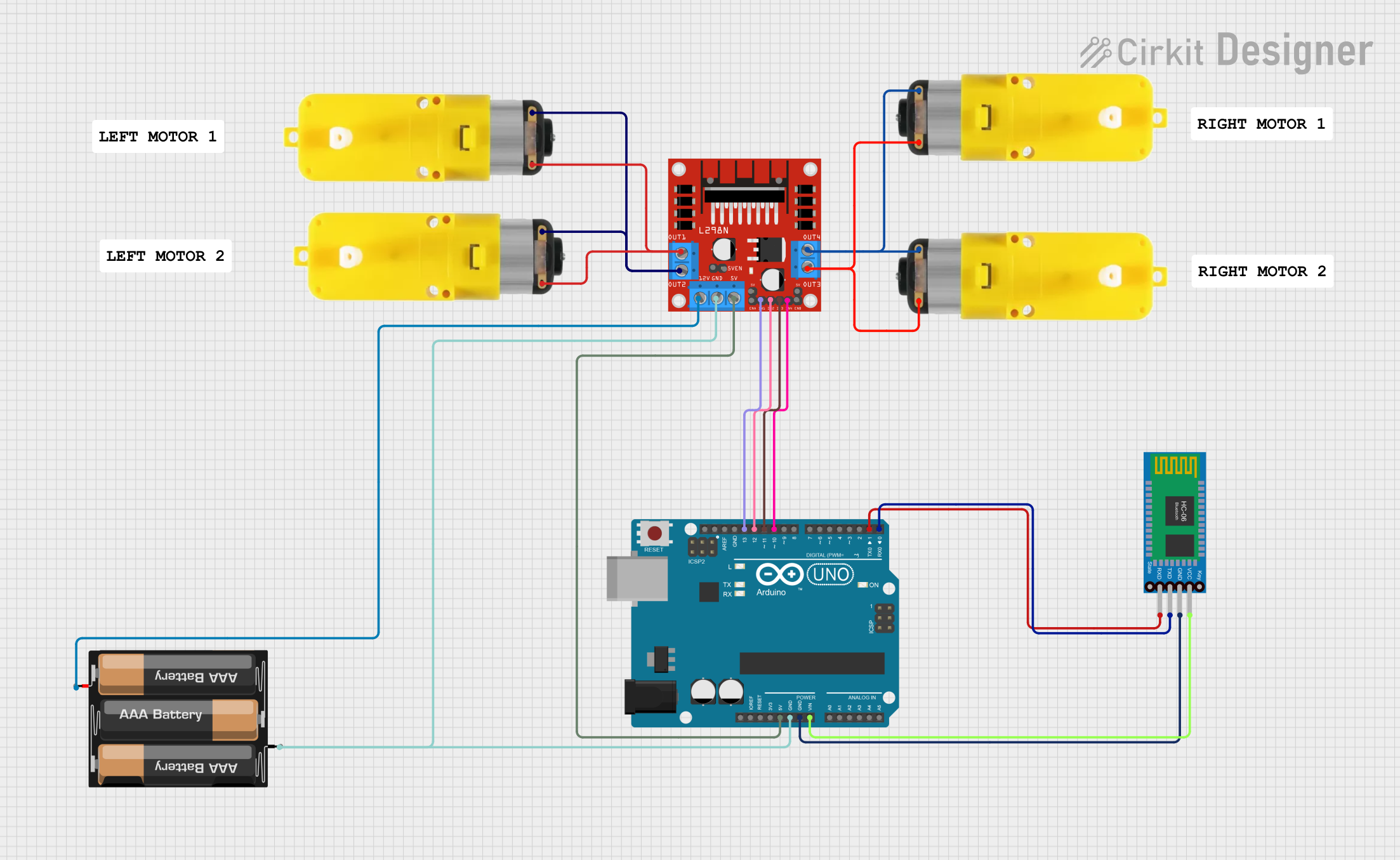
This circuit is designed to control multiple motors using an Arduino UNO microcontroller and a Bluetooth HC-06 module. The L298N motor driver is utilized to drive the motors, which are equipped with reducers for enhanced torque. The system allows for remote control of the motors via Bluetooth commands, enabling functionalities such as moving forward, backward, turning, and stopping. An LED indicator is also included to provide visual feedback.
Component List
1. Arduino UNO
- Description: A microcontroller board based on the ATmega328P. It is used to control the motors and handle Bluetooth communication.
- Purpose: Acts as the central control unit for the circuit.
2. L298N DC Motor Driver
- Description: A dual H-bridge motor driver that allows control of the direction and speed of DC motors.
- Purpose: Drives the motors based on commands received from the Arduino.
3. Motor with Reducer
- Description: A DC motor equipped with a gearbox to reduce speed and increase torque.
- Purpose: Provides the mechanical movement required for the application.
4. 3xAA Battery
- Description: A battery pack that supplies power to the circuit.
- Purpose: Provides the necessary voltage and current for the motors and the motor driver.
5. Bluetooth HC-06
- Description: A Bluetooth module that enables wireless communication between the Arduino and a Bluetooth-enabled device.
- Purpose: Receives commands from a smartphone or other Bluetooth device to control the motors.
Wiring Details
Arduino UNO
- 5V: Connected to L298N (5V)
- GND: Connected to L298N (GND)
- Vin: Connected to Bluetooth HC-06 (VCC)
- D13: Connected to L298N (IN1)
- D12: Connected to L298N (IN2)
- D11: Connected to L298N (IN3)
- D10: Connected to L298N (IN4)
- D1: Connected to Bluetooth HC-06 (RXD)
- D0: Connected to Bluetooth HC-06 (TXD)
L298N DC Motor Driver
- 5V: Connected to Arduino UNO (5V)
- GND: Connected to Arduino UNO (GND)
- 12V: Connected to 3xAA Battery (VCC)
- IN1: Connected to Arduino UNO (D13)
- IN2: Connected to Arduino UNO (D12)
- IN3: Connected to Arduino UNO (D11)
- IN4: Connected to Arduino UNO (D10)
- OUT1: Connected to Motor with Reducer (GND)
- OUT2: Connected to Motor with Reducer (3 - 6 VCC)
- OUT3: Connected to Motor with Reducer (3 - 6 VCC)
- OUT4: Connected to Motor with Reducer (GND)
Motor with Reducer
- GND: Connected to L298N (OUT1)
- 3 - 6 VCC: Connected to L298N (OUT2)
3xAA Battery
- GND: Connected to L298N (GND)
- VCC: Connected to L298N (12V)
Bluetooth HC-06
- GND: Connected to Arduino UNO (GND)
- VCC: Connected to Arduino UNO (Vin)
- RXD: Connected to Arduino UNO (D1)
- TXD: Connected to Arduino UNO (D0)
Documented Code
/*
 * This Arduino sketch controls motors via Bluetooth commands.
 * The HC-06 Bluetooth module receives commands to control the motors
 * through the L298N motor driver. An LED is used as an indicator.
 */

// Pin definitions
const int motorPin1 = 13; // IN1
const int motorPin2 = 12; // IN2
const int motorPin3 = 11; // IN3
const int motorPin4 = 10; // IN4
const int ledPin = 9;     // LED cathode

void setup() {
  // Initialize serial communication
  Serial.begin(9600);

  // Initialize motor control pins as outputs
  pinMode(motorPin1, OUTPUT);
  pinMode(motorPin2, OUTPUT);
  pinMode(motorPin3, OUTPUT);
  pinMode(motorPin4, OUTPUT);

  // Initialize LED pin as output
  pinMode(ledPin, OUTPUT);

  // Turn off motors and LED initially
  digitalWrite(motorPin1, LOW);
  digitalWrite(motorPin2, LOW);
  digitalWrite(motorPin3, LOW);
  digitalWrite(motorPin4, LOW);
  digitalWrite(ledPin, LOW);
}

void loop() {
  // Check if data is available on the serial port
  if (Serial.available() > 0) {
    char command = Serial.read();

    // Process the received command
    switch (command) {
      case 'F': // Move forward
        digitalWrite(motorPin1, HIGH);
        digitalWrite(motorPin2, LOW);
        digitalWrite(motorPin3, HIGH);
        digitalWrite(motorPin4, LOW);
        break;
      case 'B': // Move backward
        digitalWrite(motorPin1, LOW);
        digitalWrite(motorPin2, HIGH);
        digitalWrite(motorPin3, LOW);
        digitalWrite(motorPin4, HIGH);
        break;
      case 'L': // Turn left
        digitalWrite(motorPin1, LOW);
        digitalWrite(motorPin2, HIGH);
        digitalWrite(motorPin3, HIGH);
        digitalWrite(motorPin4, LOW);
        break;
      case 'R': // Turn right
        digitalWrite(motorPin1, HIGH);
        digitalWrite(motorPin2, LOW);
        digitalWrite(motorPin3, LOW);
        digitalWrite(motorPin4, HIGH);
        break;
      case 'S': // Stop
        digitalWrite(motorPin1, LOW);
        digitalWrite(motorPin2, LOW);
        digitalWrite(motorPin3, LOW);
        digitalWrite(motorPin4, LOW);
        break;
      case 'O': // Turn on LED
        digitalWrite(ledPin, HIGH);
        break;
      case 'f': // Turn off LED
        digitalWrite(ledPin, LOW);
        break;
      default:
        // Unknown command
        break;
    }
  }
}
This documentation provides a comprehensive overview of the circuit, detailing the components used, their connections, and the code that drives the functionality.