Cirkit Designer
Your all-in-one circuit design IDE
Home /
Project Documentation
Dual Arduino UNO Controlled Servo Motors for Robotics
Circuit Documentation
Summary
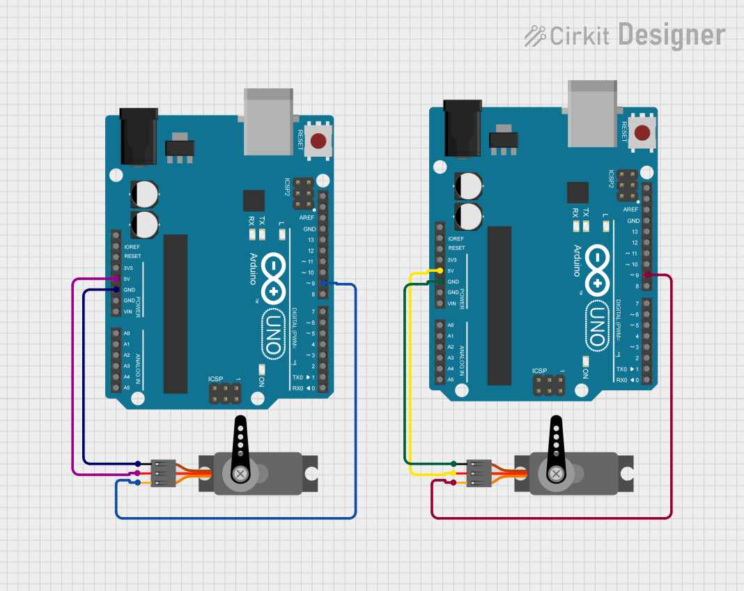
This circuit involves two Arduino UNO microcontrollers, each controlling a separate servo motor. The servos are powered and controlled by the respective Arduino boards. The setup includes connections for power, ground, and PWM signals to control the servos.
Component List
Arduino UNO
- Description: A microcontroller board based on the ATmega328P.
- Pins: UNUSED, IOREF, Reset, 3.3V, 5V, GND, Vin, A0, A1, A2, A3, A4, A5, SCL, SDA, AREF, D13, D12, D11, D10, D9, D8, D7, D6, D5, D4, D3, D2, D1, D0
Servo
- Description: A motor that can be controlled to move to a specific position.
- Pins: GND, VCC, PWM
Wiring Details
Arduino UNO (1)
- 5V: Connected to VCC of Servo (1)
- GND: Connected to GND of Servo (1)
- D9: Connected to PWM of Servo (1)
Servo (1)
- VCC: Connected to 5V of Arduino UNO (1)
- GND: Connected to GND of Arduino UNO (1)
- PWM: Connected to D9 of Arduino UNO (1)
Arduino UNO (2)
- 5V: Connected to VCC of Servo (2)
- GND: Connected to GND of Servo (2)
- D9: Connected to PWM of Servo (2)
Servo (2)
- VCC: Connected to 5V of Arduino UNO (2)
- GND: Connected to GND of Arduino UNO (2)
- PWM: Connected to D9 of Arduino UNO (2)
Code Documentation
Arduino UNO (1)
void setup() {
  // put your setup code here, to run once:

}

void loop() {
  // put your main code here, to run repeatedly:

}
Arduino UNO (2)
void setup() {
  // put your setup code here, to run once:

}

void loop() {
  // put your main code here, to run repeatedly:

}
This documentation provides a comprehensive overview of the circuit, including a summary, detailed component list, wiring details, and the code used for the microcontrollers.