
ESP8266 Wi-Fi Controlled Gas and IR Sensor System with OLED Display
View and Edit Project In Cirkit Designer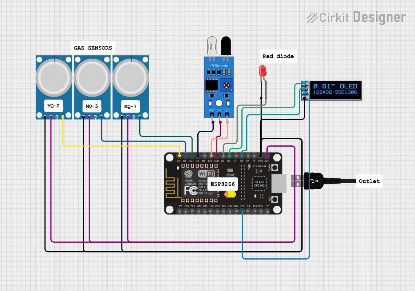
Circuit Documentation
Summary
This document provides a detailed overview of a circuit that includes an ESP8266 NodeMCU microcontroller, multiple MQ-2 gas sensors, an IR sensor, an OLED display, and an LED. The circuit is designed to interface these components with the ESP8266 for various sensing and display purposes.
Component List
ESP8266 NodeMCU
- Description: A low-cost Wi-Fi microcontroller with GPIO, ADC, and other interfaces.
- Pins: D0, D1, D2, D3, D4, 3V3, GND, D5, D6, D7, D8, RX, TX, A0, RSV, SD3, SD2, SD1, CMD, SD0, CLK, EN, RST, VIN
USB Male 2 Pin Connection
- Description: A standard USB male connector for power supply.
- Pins: Negative -, Positive +
MQ-2 Gas Sensor
- Description: A gas sensor for detecting LPG, i-butane, propane, methane, alcohol, hydrogen, and smoke.
- Pins: GND, VCC, ANALOG, Digital
IR Sensor
- Description: An infrared sensor for object detection.
- Pins: out, gnd, vcc
LED: Two Pin (Red)
- Description: A standard red LED.
- Pins: cathode, anode
OLED Display 128x32
- Description: A 128x32 pixel OLED display.
- Pins: SDA, SCL, VCC, GND
Wiring Details
ESP8266 NodeMCU
- D0: Connected to Digital pin of MQ-2 (Instance 1)
- D1: Connected to Digital pin of MQ-2 (Instance 2)
- D2: Connected to Digital pin of MQ-2 (Instance 3)
- D3: Connected to out pin of IR sensor
- D5: Connected to anode of LED
- D6: Connected to SDA pin of OLED display
- D8: Connected to SCL pin of OLED display
- 3V3: Connected to vcc pin of IR sensor, VCC pins of all MQ-2 sensors, and VCC pin of OLED display
- GND: Connected to gnd pin of IR sensor, GND pins of all MQ-2 sensors, GND pin of OLED display, and cathode of LED
USB Male 2 Pin Connection
- Negative -: Not connected in the provided net list
- Positive +: Not connected in the provided net list
MQ-2 Gas Sensor (Instance 1)
- Digital: Connected to D0 pin of ESP8266
- GND: Connected to GND pin of ESP8266
- VCC: Connected to 3V3 pin of ESP8266
MQ-2 Gas Sensor (Instance 2)
- Digital: Connected to D1 pin of ESP8266
- GND: Connected to GND pin of ESP8266
- VCC: Connected to 3V3 pin of ESP8266
MQ-2 Gas Sensor (Instance 3)
- Digital: Connected to D2 pin of ESP8266
- GND: Connected to GND pin of ESP8266
- VCC: Connected to 3V3 pin of ESP8266
IR Sensor
- out: Connected to D3 pin of ESP8266
- gnd: Connected to GND pin of ESP8266
- vcc: Connected to 3V3 pin of ESP8266
LED: Two Pin (Red)
- anode: Connected to D5 pin of ESP8266
- cathode: Connected to GND pin of ESP8266
OLED Display 128x32
- SDA: Connected to D6 pin of ESP8266
- SCL: Connected to D8 pin of ESP8266
- VCC: Connected to 3V3 pin of ESP8266
- GND: Connected to GND pin of ESP8266
Code
No code was provided for this circuit.
This document provides a comprehensive overview of the circuit, including a summary, component list, wiring details, and code section. Each component is described, and its connections are detailed to ensure clarity and ease of understanding.