Cirkit Designer
Your all-in-one circuit design IDE
Home /
Project Documentation
Arduino UNO with LDR-Controlled LED and HC-05 Bluetooth Module
Circuit Documentation
Summary of the Circuit
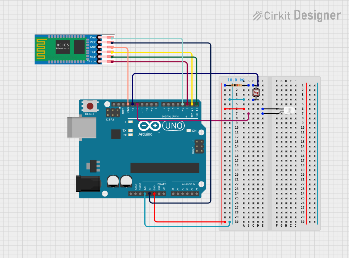
This circuit appears to be designed for sensing ambient light levels using a photocell (LDR) and controlling an LED based on the sensed values. It also includes an HC-05 Bluetooth module for potential wireless communication. The Arduino UNO serves as the central microcontroller to process sensor data and control the LED. The circuit is powered by the Arduino UNO's voltage supply pins.
Component List
Arduino UNO
- Microcontroller board based on the ATmega328P
- It has 14 digital input/output pins, 6 analog inputs, a 16 MHz quartz crystal, a USB connection, a power jack, an ICSP header, and a reset button.
Resistor
- A passive two-terminal electrical component that implements electrical resistance as a circuit element.
- Resistance: 10,000 Ohms
LED: Two Pin (white)
- A basic white light-emitting diode.
- It has an anode and a cathode for connecting to a power source.
Photocell (LDR)
- A light-dependent resistor whose resistance decreases with increasing incident light intensity.
- It can be used to detect light levels.
HC-05
- A commonly used Bluetooth module for wireless communication.
- It has pins for enabling the device, power supply, ground, transmit and receive data, and state indication.
Wiring Details
Arduino UNO
- D13: Connected to the Resistor and Photocell (LDR)
- 3.3V: Connected to the Photocell (LDR)
- GND: Connected to the LED (cathode) and HC-05 (GND)
- D12: Connected to the LED (anode)
- 5V: Connected to HC-05 (VCC)
- D3: Connected to HC-05 (EN)
- D2: Connected to HC-05 (STATE)
- D1: Connected to HC-05 (TXD)
- D0: Connected to HC-05 (RXD)
Resistor
- Pin1: Connected to the LED (cathode)
- Pin2: Connected to the Photocell (LDR) and Arduino UNO (D13)
LED: Two Pin (white)
- Anode: Connected to Arduino UNO (D12)
- Cathode: Connected to the Resistor (Pin1) and Arduino UNO (GND)
Photocell (LDR)
- Pin 0: Connected to the Resistor (Pin2) and Arduino UNO (D13)
- Pin 1: Connected to Arduino UNO (3.3V)
HC-05
- EN: Connected to Arduino UNO (D3)
- VCC: Connected to Arduino UNO (5V)
- GND: Connected to Arduino UNO (GND)
- TXD: Connected to Arduino UNO (D1)
- RXD: Connected to Arduino UNO (D0)
- STATE: Connected to Arduino UNO (D2)
Documented Code
Arduino UNO Code (sketch.ino)
void setup() {
  // put your setup code here, to run once:

}

void loop() {
  // put your main code here, to run repeatedly:

}
Note: The provided code is a template and does not include any functionality. It needs to be populated with the logic for reading the photocell, controlling the LED, and managing Bluetooth communication with the HC-05 module.