
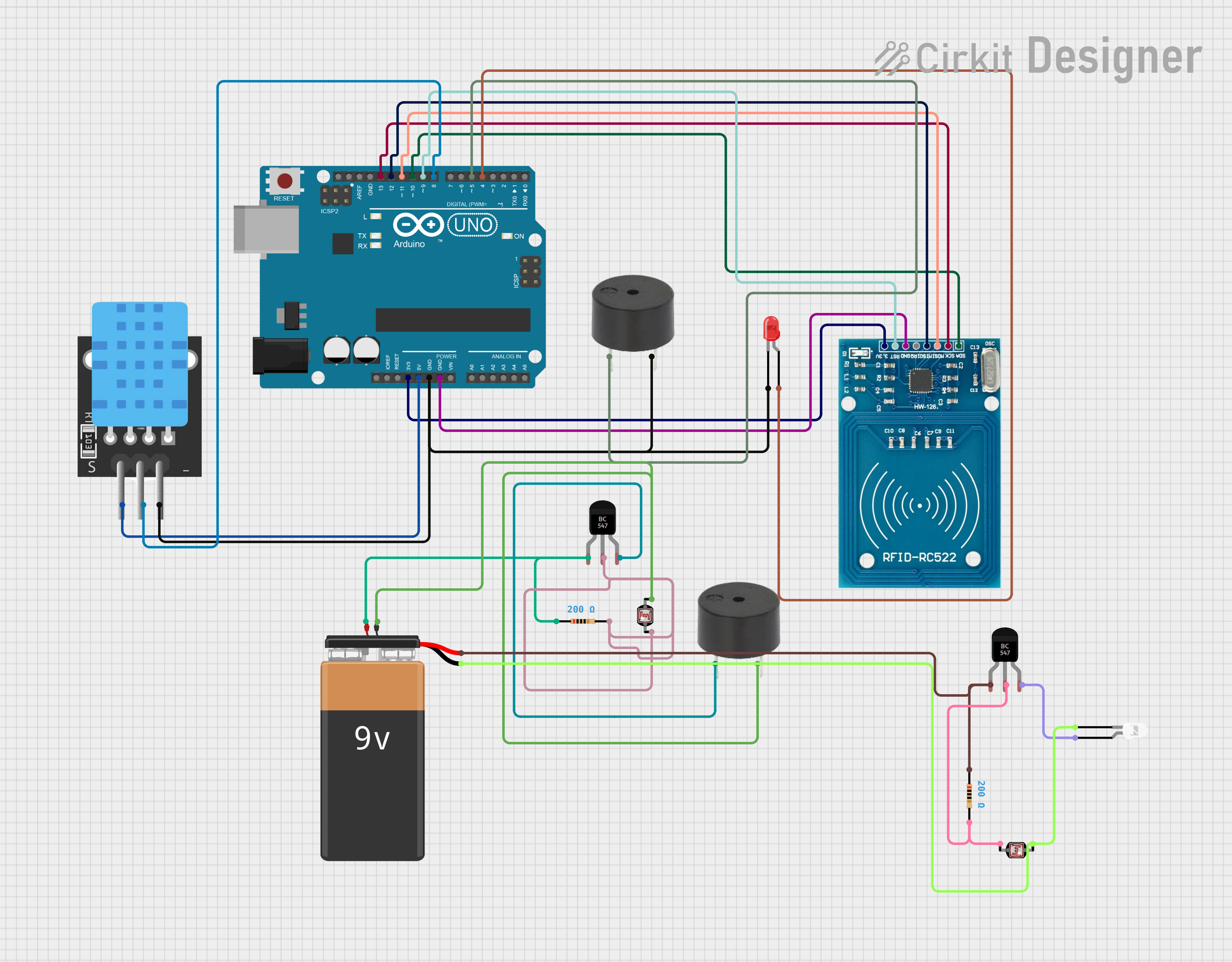
Circuit Documentation
Summary
This circuit integrates various components with an Arduino UNO microcontroller to perform tasks involving RFID reading, temperature sensing, light detection, and signaling through LEDs and buzzers. The circuit is powered by a 9V battery and utilizes transistors and resistors to control the flow and distribution of power to different components.
Component List
Arduino UNO
- Microcontroller board based on the ATmega328P
- It has 14 digital input/output pins, 6 analog inputs, a 16 MHz quartz crystal, a USB connection, a power jack, an ICSP header, and a reset button.
Photocell (LDR)
- A light-dependent resistor whose resistance varies with the amount of light it is exposed to.
RFID-RC522
- An RFID reader/writer module that operates at 13.56 MHz.
TEMP
- A temperature sensor component.
BC547 Transistor
- A general-purpose NPN bipolar junction transistor used for switching and amplification.
Battery 9V
- A standard 9-volt battery used to power the circuit.
Resistor
- A passive two-terminal electrical component that implements electrical resistance as a circuit element.
LED: Two Pin (red/white)
- A light-emitting diode that emits red or white light when powered.
Buzzer
- An audio signaling device that can be mechanical, electromechanical, or piezoelectric.
Wiring Details
Arduino UNO
3.3Vconnected to RFID-RC522 VCC (3.3V)5Vconnected to TEMP 5VGNDconnected to buzzer GND, LED (red) cathode, TEMP GND, RFID-RC522 GNDD13connected to RFID-RC522 SCKD12connected to RFID-RC522 MISOD11connected to RFID-RC522 MOSID10connected to RFID-RC522 SDAD9connected to RFID-RC522 RSTD8connected to TEMP D3D5connected to buzzer PIND4connected to LED (red) anode
Photocell (LDR)
pin 0connected to 9V Battery (-) and LED (white) cathodepin 1connected to BC547 Transistor Base and buzzer GND
RFID-RC522
- Connections to Arduino UNO as detailed above.
TEMP
5VandGNDconnected to Arduino UNO 5V and GND respectivelyD3connected to Arduino UNO D8
BC547 Transistor
Baseconnected to Photocell (LDR) pin 1 and Resistor pin2Collectorconnected to 9V Battery (+) and Resistor pin1Emitterconnected to LED (white) anode and buzzer PIN
Battery 9V
VCCconnected to BC547 Transistor CollectorGNDconnected to Photocell (LDR) pin 0
Resistor
pin1connected to BC547 Transistor Collectorpin2connected to BC547 Transistor Base
LED: Two Pin (red/white)
cathodeconnected to Arduino UNO GND and Photocell (LDR) pin 0anodeconnected to Arduino UNO D4 and BC547 Transistor Emitter
Buzzer
PINconnected to Arduino UNO D5 and BC547 Transistor EmitterGNDconnected to Arduino UNO GND and Photocell (LDR) pin 1
Documented Code
Arduino UNO Code (sketch.ino)
void setup() {
  // put your setup code here, to run once:

}

void loop() {
  // put your main code here, to run repeatedly:

}
Note: The provided code is a template and does not contain any functional code. It needs to be populated with the logic to control the RFID-RC522, read the TEMP sensor, detect light with the LDR, and activate the LEDs and buzzers accordingly.