
Circuit Documentation
Summary
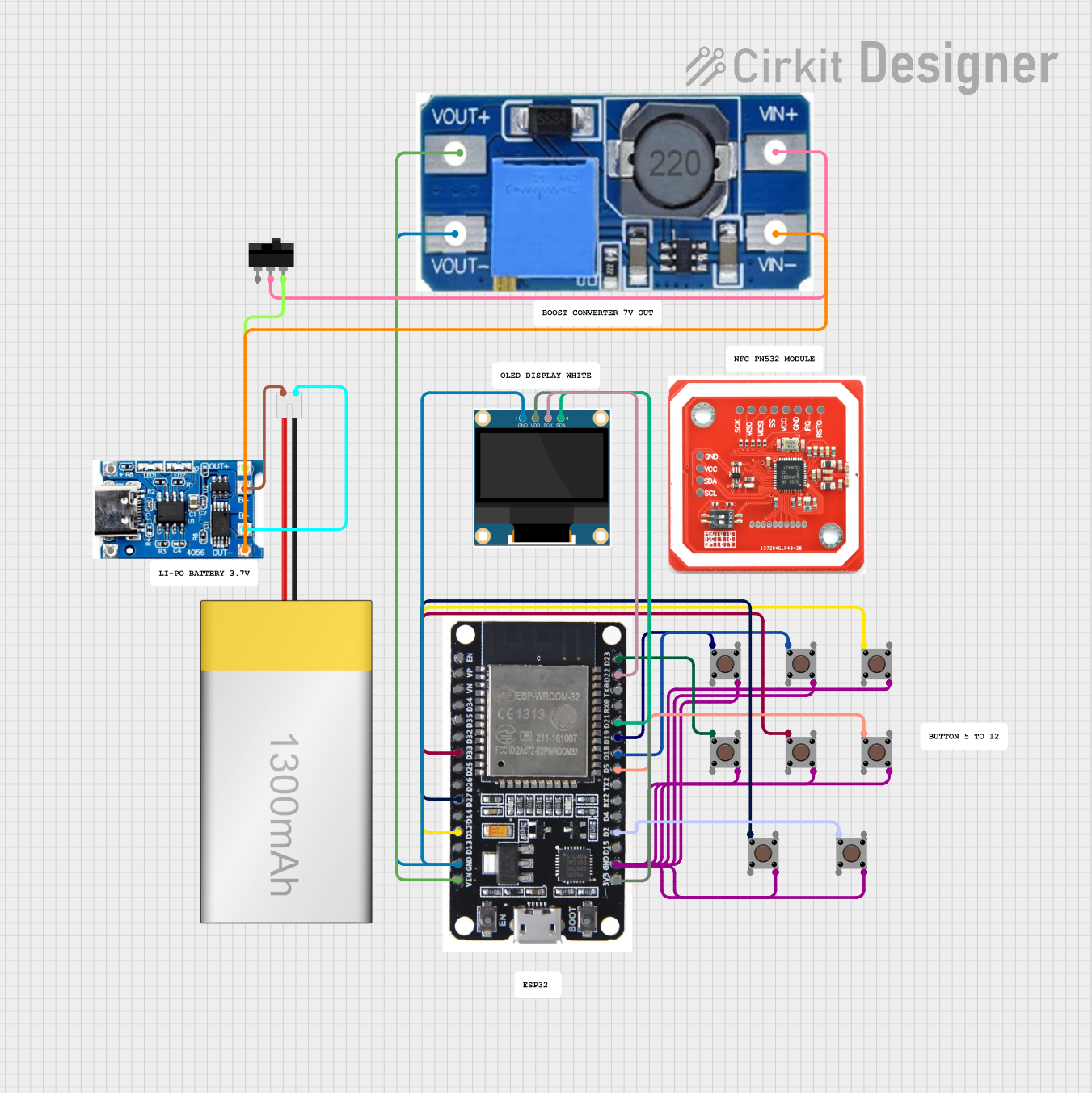
The circuit in question appears to be a microcontroller-based system with an ESP32 at its core, interfacing with a 0.96" OLED display and multiple pushbuttons. The ESP32 is responsible for handling inputs from the pushbuttons and displaying relevant information on the OLED screen. The circuit also includes a power management system with a LiPoly battery, a TP4056 battery charging module, and a step-up boost power converter to provide a stable voltage supply to the ESP32 and the OLED display. A toggle switch is included to control the power flow from the battery to the power converter.
Component List
Microcontroller
- ESP32: A microcontroller with Wi-Fi and Bluetooth capabilities, featuring a wide range of GPIO pins for interfacing with various peripherals.
Display
- 0.96" OLED: A small display that uses the I2C protocol for communication, suitable for displaying text and graphics.
Input Devices
- Pushbuttons: Multiple instances of a simple pushbutton used as a digital input device to the ESP32.
Power Management
- LiPoly Battery (1300mAh): A rechargeable lithium polymer battery that provides power to the circuit.
- TP4056 Battery Charging Protection Module (Type C): A module used for charging the LiPoly battery and providing protection against overcharging.
- Step Up Boost Power Converter, Adjustable Voltage Regulator: A module that steps up the voltage from the battery to a required level for the ESP32 and OLED display.
- Toggle Switch: A switch used to control the power supply to the circuit.
Communication
- NFC/RFID reader PN532: A reader module for Near Field Communication (NFC) or Radio-Frequency Identification (RFID), although its connections are not specified in the provided net list.
Wiring Details
ESP32
- GND: Connected to the OLED GND, Step Up Boost Power Converter VOUT-, and all pushbutton Pin 4 (out) pins.
- 3V3: Powers the OLED VDD.
- D22: Connected to the OLED SCK.
- D21: Connected to the OLED SDA.
- D33, D27, D12, D2, D5, D18, D19, D23: Each connected to a different pushbutton Pin 1 (in).
- VIN: Connected to the Step Up Boost Power Converter VOUT+.
0.96" OLED
- GND: Connected to ESP32 GND.
- VDD: Powered by ESP32 3V3.
- SCK: Receives clock signal from ESP32 D22.
- SDA: Receives data from ESP32 D21.
Pushbuttons
- Pin 1 (in): Each button is connected to a unique GPIO on the ESP32.
- Pin 4 (out): All buttons share a common ground connection with the ESP32 GND.
Power Management
- LiPoly Battery (1300mAh): Provides power to the TP4056 module.
- TP4056 Battery Charging Protection Module (Type C): Charges the battery and connects to the Step Up Boost Power Converter through the Toggle Switch.
- Step Up Boost Power Converter, Adjustable Voltage Regulator: Steps up the battery voltage and provides power to the ESP32 VIN.
- Toggle Switch: Controls the connection between the TP4056 OUT+ and the Step Up Boost Power Converter VIN+.
Documented Code
No code was provided for the microcontroller(s) in the circuit. Therefore, this section is not applicable to the current documentation.