Arduino UNO Controlled LED Indicator
Circuit Documentation
Summary
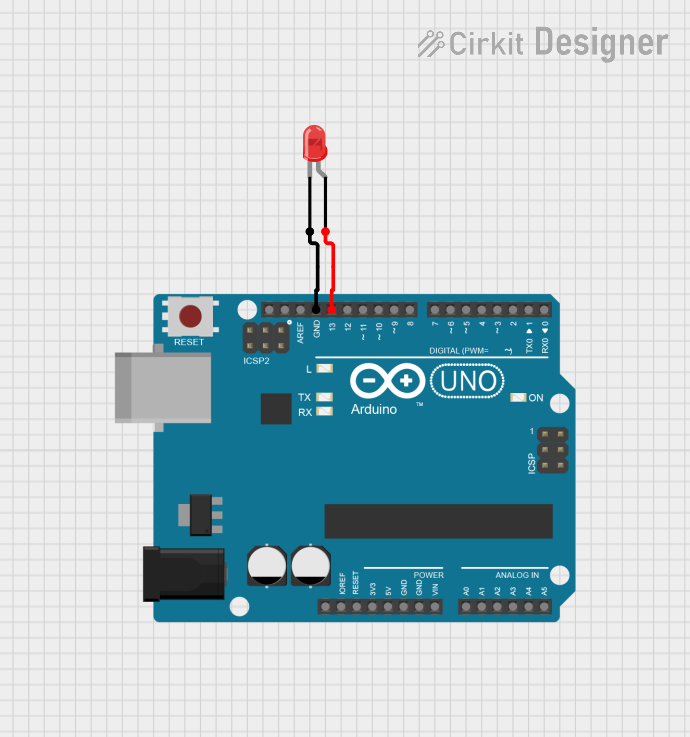
This circuit consists of an Arduino UNO microcontroller and a red LED. The LED is connected to the Arduino UNO such that it can be controlled via one of the digital output pins. The cathode of the LED is connected to the ground (GND) pin of the Arduino, and the anode is connected to the digital pin 13 (D13) of the Arduino.
Component List
Arduino UNO
- Description: A microcontroller board based on the ATmega328P.
- Pins: UNUSED, IOREF, Reset, 3.3V, 5V, GND, Vin, A0, A1, A2, A3, A4, A5, SCL, SDA, AREF, D13, D12, D11, D10, D9, D8, D7, D6, D5, D4, D3, D2, D1, D0
- Purpose in Circuit: Acts as the main controller for the circuit, providing power and control signals to the LED.
LED: Two Pin (red)
- Description: A red light-emitting diode.
- Pins: cathode, anode
- Purpose in Circuit: Provides visual feedback by emitting light when powered.
Wiring Details
Arduino UNO
- GND: Connected to the cathode of the LED.
- D13: Connected to the anode of the LED.
LED: Two Pin (red)
- cathode: Connected to the GND pin of the Arduino UNO.
- anode: Connected to the D13 pin of the Arduino UNO.
Documented Code
Arduino UNO Code
void setup() {
  // put your setup code here, to run once:

}

void loop() {
  // put your main code here, to run repeatedly:

}
This code is a basic template for the Arduino UNO. The setup() function is where you initialize settings, and the loop() function is where the main code runs repeatedly. In this circuit, you would typically add code to control the LED connected to pin D13. For example, you could turn the LED on and off by setting the pin high and low, respectively.
Additional Documentation
This section is reserved for any additional documentation or notes related to the circuit and its operation.