
Arduino Nano-Based Health Monitoring System with OLED Display and Battery Power
View and Edit Project In Cirkit Designer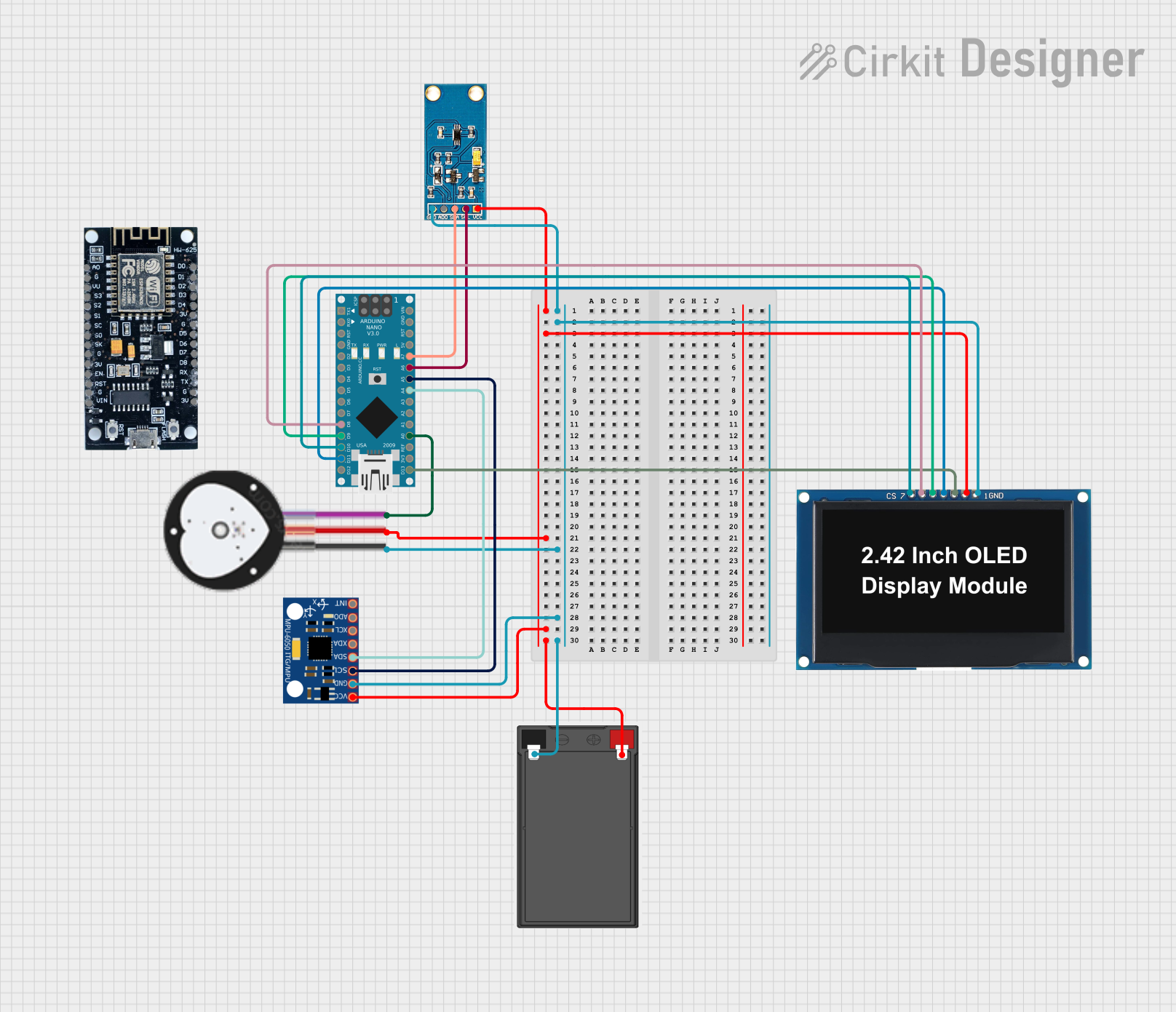
Circuit Documentation
Summary
This document provides a detailed overview of a circuit that includes an Arduino Nano, a light sensor, a heart pulse sensor, an MPU-6050 accelerometer and gyroscope, an OLED display, an ESP8266 Wi-Fi module, and a battery. The circuit is designed to interface various sensors and display data on the OLED screen, with potential for wireless communication via the ESP8266.
Component List
Arduino Nano
- Description: A small, complete, and breadboard-friendly board based on the ATmega328P.
- Pins: D1/TX, D0/RX, RESET, GND, D2, D3, D4, D5, D6, D7, D8, D9, D10, D11/MOSI, D12/MISO, VIN, 5V, A7, A6, A5, A4, A3, A2, A1, A0, AREF, 3V3, D13/SCK
Light Sensor
- Description: A sensor used to detect light intensity.
- Pins: VCC, SCL, SDA, ADD, GND
Heart Pulse Sensor
- Description: A sensor used to measure heart rate.
- Pins: GND, VCC, SIGNAL
MPU-6050
- Description: A 6-axis motion tracking device that combines a 3-axis gyroscope and a 3-axis accelerometer.
- Pins: VCC, GND, SCL, SDA, XDA, XCL, AD0, INT
Battery
- Description: A power source for the circuit.
- Pins: -, +
OLED Display 2.42"
- Description: A small display used to show information.
- Pins: GND, VCC, SCK, SDA, RES, DC, CS
ESP8266
- Description: A Wi-Fi module used for wireless communication.
- Pins: 3V, G, D8, D7, D6, D5, D4, D3, D2, D1, D0, A0, S3, S2, S1, SC, S0, SK, EN, VIN, RST, VU
Wiring Details
Arduino Nano
- D8: Connected to OLED Display DC
- D9: Connected to OLED Display RES
- D10: Connected to OLED Display CS
- D11/MOSI: Connected to OLED Display SDA
- A7: Connected to Light Sensor SDA
- A6: Connected to Light Sensor SCL
- A5: Connected to MPU-6050 SCL
- A4: Connected to MPU-6050 SDA
- A0: Connected to Heart Pulse Sensor SIGNAL
- D13/SCK: Connected to OLED Display SCK
Light Sensor
- VCC: Connected to Battery +
- GND: Connected to Battery -
- SDA: Connected to Arduino Nano A7
- SCL: Connected to Arduino Nano A6
Heart Pulse Sensor
- VCC: Connected to Battery +
- GND: Connected to Battery -
- SIGNAL: Connected to Arduino Nano A0
MPU-6050
- VCC: Connected to Battery +
- GND: Connected to Battery -
- SCL: Connected to Arduino Nano A5
- SDA: Connected to Arduino Nano A4
Battery
- +: Connected to Light Sensor VCC, Heart Pulse Sensor VCC, MPU-6050 VCC, OLED Display VCC
- -: Connected to Light Sensor GND, Heart Pulse Sensor GND, MPU-6050 GND, OLED Display GND
OLED Display 2.42"
- VCC: Connected to Battery +
- GND: Connected to Battery -
- SCK: Connected to Arduino Nano D13/SCK
- SDA: Connected to Arduino Nano D11/MOSI
- RES: Connected to Arduino Nano D9
- DC: Connected to Arduino Nano D8
- CS: Connected to Arduino Nano D10
ESP8266
- Not connected in this circuit
Documented Code
Arduino Nano Code (sketch.ino)
void setup() {
  // put your setup code here, to run once:

}

void loop() {
  // put your main code here, to run repeatedly:

}
Additional Documentation (documentation.txt)
This document provides a comprehensive overview of the circuit, including a summary, component list, wiring details, and documented code.