
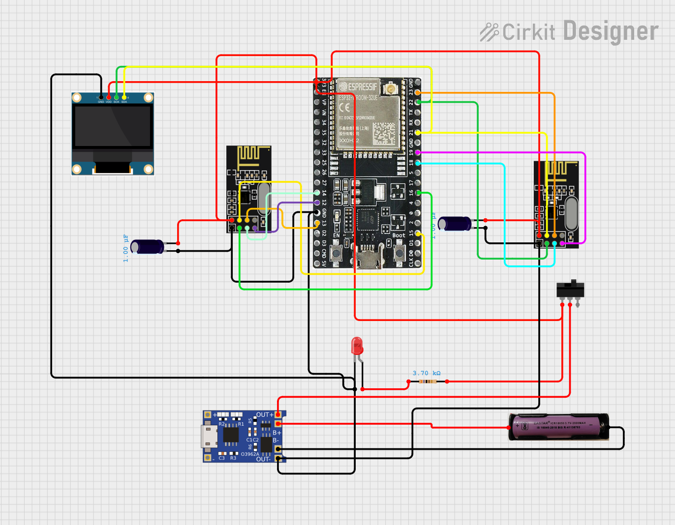
Circuit Documentation
Summary
This document provides a detailed overview of a circuit designed to perform various tasks, including Wi-Fi and Bluetooth jamming. The circuit consists of multiple components, including capacitors, resistors, LEDs, a toggle switch, a TP4056 battery charger, NRF24L01 modules, an ESP32 microcontroller, and an OLED display. The document includes a component list, wiring details, and documented code for the microcontrollers.
Component List
Electrolytic Capacitor
- Description: A capacitor used for filtering and energy storage.
- Pins: -, +
- Properties:
- Capacitance: 0.000001 Farads
Resistor
- Description: A resistor used to limit current.
- Pins: pin1, pin2
- Properties:
- Resistance: 3700 Ohms
LED: Two Pin (red)
- Description: A red LED used for indication.
- Pins: cathode, anode
Toggle Switch
- Description: A switch used to control the circuit.
- Pins: L1, COM, L2
TP4056
- Description: A battery charger module.
- Pins: OUT-, B-, B+, OUT+, IN-, IN+
NRF24L01
- Description: A wireless transceiver module.
- Pins: IRQ (not used), MOSI, CSN, VCC (3V), GND, CE, SCK, MISO
3.7v Battery
- Description: A 3.7V battery used to power the circuit.
- Pins: +, -
ESP32-WROOM-32UE
- Description: A microcontroller with Wi-Fi and Bluetooth capabilities.
- Pins: 3v3, EN, VP, VN, 34, 35, 32, 33, 25, 26, 27, 14, 12, GND, 13, D2, D3, 5V, 23, 22, TX, RX, 21, 19, 18, 5, 17, 16, 4, 0, 2, 15, D1, D0, CKL
0.96" OLED
- Description: An OLED display used for visual output.
- Pins: GND, VDD, SCK, SDA
Wiring Details
Electrolytic Capacitor
- Pin -: Connected to GND (common ground with other components)
- Pin +: Connected to VCC (common power with other components)
Resistor
- Pin 1: Connected to the anode of the LED
- Pin 2: Connected to VCC (common power with other components)
LED: Two Pin (red)
- Cathode: Connected to GND (common ground with other components)
- Anode: Connected to pin1 of the resistor
Toggle Switch
- L1: Connected to VCC (common power with other components)
- COM: Connected to OUT+ of the TP4056
- L2: Not connected
TP4056
- OUT-: Connected to GND (common ground with other components)
- B-: Connected to - of the 3.7v battery
- B+: Connected to + of the 3.7v battery
- OUT+: Connected to COM of the toggle switch
- IN-: Not connected
- IN+: Not connected
NRF24L01 (Module 1)
- GND: Connected to GND (common ground with other components)
- VCC (3V): Connected to VCC (common power with other components)
- MOSI: Connected to pin 13 of the ESP32
- CSN: Connected to pin 15 of the ESP32
- CE: Connected to pin 16 of the ESP32
- SCK: Connected to pin 14 of the ESP32
- MISO: Connected to pin 12 of the ESP32
NRF24L01 (Module 2)
- GND: Connected to GND (common ground with other components)
- VCC (3V): Connected to VCC (common power with other components)
- MOSI: Connected to pin 23 of the ESP32
- CSN: Connected to pin 21 of the ESP32
- CE: Connected to pin 22 of the ESP32
- SCK: Connected to pin 18 of the ESP32
- MISO: Connected to pin 19 of the ESP32
3.7v Battery
- -: Connected to B- of the TP4056
- +: Connected to B+ of the TP4056
ESP32-WROOM-32UE
- GND: Connected to GND (common ground with other components)
- 3v3: Connected to VCC (common power with other components)
- Pin 13: Connected to MOSI of NRF24L01 (Module 1)
- Pin 15: Connected to CSN of NRF24L01 (Module 1)
- Pin 16: Connected to CE of NRF24L01 (Module 1)
- Pin 14: Connected to SCK of NRF24L01 (Module 1)
- Pin 12: Connected to MISO of NRF24L01 (Module 1)
- Pin 23: Connected to MOSI of NRF24L01 (Module 2)
- Pin 21: Connected to CSN of NRF24L01 (Module 2)
- Pin 22: Connected to CE of NRF24L01 (Module 2)
- Pin 18: Connected to SCK of NRF24L01 (Module 2)
- Pin 19: Connected to MISO of NRF24L01 (Module 2)
0.96" OLED
- GND: Connected to GND (common ground with other components)
- VDD: Connected to VCC (common power with other components)
- SCK: Connected to pin 22 of the ESP32
- SDA: Connected to pin 21 of the ESP32
Documented Code
LED: Two Pin (red)
void setup() {
  // put your setup code here, to run once:

}

void loop() {
  // put your main code here, to run repeatedly:

}
ESP32-WROOM-32UE
#include <SPI.h>
#include <nRF24L01.h>
#include <RF24.h>

// NRF24L01 Module 1 Pins (for Wi-Fi jamming)
#define CE_PIN1 22
#define CSN_PIN1 21

// NRF24L01 Module 2 Pins (for Bluetooth jamming)
#define CE_PIN2 16
#define CSN_PIN2 15

// Control pins (switches/buttons)
#define WIFI_CONTROL_PIN 4    // GPIO 4 to control Wi-Fi jamming
#define BT_CONTROL_PIN 5      // GPIO 5 to control Bluetooth jamming
#define BOOT_BUTTON_PIN 0     // GPIO 0 for boot button to change modes

// Create RF24 instances
RF24 wifiJammer(CE_PIN1, CSN_PIN1);
RF24 btJammer(CE_PIN2, CSN_PIN2);

// Dummy payload for interference (repeated noisy data)
const char interferencePayload[32] = "NOISE_INTERFERENCE_DATA";

// Mode definitions
enum Mode {
  IDLE,
  WIFI_JAMMING,
  BT_JAMMING,
  RC_DRONE_JAMMING
};

Mode currentMode = IDLE;

// Bluetooth channels (79 channels from 2.402 GHz to 2.480 GHz)
const uint8_t btChannels[79] = {
  2, 3, 4, 5, 6, 7, 8, 9, 10, 11, 12, 13, 14, 15, 16, 17, 18, 19, 20, 21, 22, 23, 24, 25, 26, 27, 28, 29, 30, 31, 32, 33, 34, 35, 36, 37, 38, 39, 40, 41, 42, 43, 44, 45, 46, 47, 48, 49, 50, 51, 52, 53, 54, 55, 56, 57, 58, 59, 60, 61, 62, 63, 64, 65, 66, 67, 68, 69, 70, 71, 72, 73, 74, 75, 76, 77, 78, 79, 80
};

// Wi-Fi channels (11 channels from 2.412 GHz to 2.484 GHz)
const uint8_t wifiChannels[11] = {
  1, 6, 11, 2, 7, 3, 8, 4, 9, 5, 10
};

// RC Drone channels (common channels within 2.4 GHz band)
const uint