
Circuit Documentation
Summary
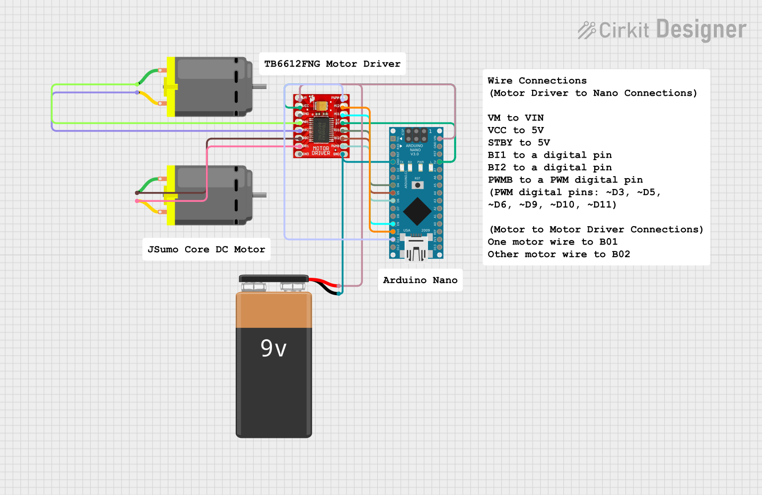
This document provides a detailed overview of a circuit that primarily consists of an Arduino Nano microcontroller, a TB6612FNG Motor Driver, two DC Motors, and a 9V Battery. The circuit is designed to control the two DC Motors using the motor driver, which is interfaced with the Arduino Nano. The Arduino Nano is responsible for providing control signals to the motor driver, which in turn drives the motors. The 9V Battery supplies power to the system.
Component List
Arduino Nano
- Description: A compact microcontroller board based on the ATmega328P.
- Purpose: Acts as the central controller for the circuit, providing logic and control signals to the motor driver.
DC Motor (x2)
- Description: An electric motor that runs on direct current (DC) electricity.
- Purpose: The motors are the actuators in the circuit, responsible for converting electrical energy into mechanical motion.
TB6612FNG Motor Driver
- Description: A motor driver IC capable of driving two DC motors.
- Purpose: Interfaces between the Arduino Nano and the DC Motors, providing the necessary current and direction control for the motors.
9V Battery
- Description: A standard 9V battery.
- Purpose: Provides the power source for the motor driver and the Arduino Nano.
Wiring Details
Arduino Nano
- GND connected to the ground of the TB6612FNG Motor Driver and the negative terminal of the 9V Battery.
- D4 connected to the BI1 pin of the TB6612FNG Motor Driver.
- D5 connected to the BI2 pin of the TB6612FNG Motor Driver.
- D6 connected to the PWMB pin of the TB6612FNG Motor Driver.
- D9 connected to the AI1 pin of the TB6612FNG Motor Driver.
- D10 connected to the AI2 pin of the TB6612FNG Motor Driver.
- D11/MOSI connected to the PWMA pin of the TB6612FNG Motor Driver.
- VIN connected to the VM pin of the TB6612FNG Motor Driver and the positive terminal of the 9V Battery.
- 5V connected to the VCC and STBY pins of the TB6612FNG Motor Driver.
DC Motor 1
- Pin 1 connected to the B02 pin of the TB6612FNG Motor Driver.
- Pin 2 connected to the B01 pin of the TB6612FNG Motor Driver.
DC Motor 2
- Pin 1 connected to the A01 pin of the TB6612FNG Motor Driver.
- Pin 2 connected to the A02 pin of the TB6612FNG Motor Driver.
TB6612FNG Motor Driver
- GND connected to the ground of the Arduino Nano and the negative terminal of the 9V Battery.
- BI1, BI2, PWMB, AI1, AI2, PWMA connected to respective pins on the Arduino Nano as detailed above.
- VM connected to the positive terminal of the 9V Battery and the VIN pin of the Arduino Nano.
- VCC, STBY connected to the 5V pin of the Arduino Nano.
- B01, B02 connected to the respective pins of DC Motor 1.
- A01, A02 connected to the respective pins of DC Motor 2.
9V Battery
- + connected to the VM pin of the TB6612FNG Motor Driver and the VIN pin of the Arduino Nano.
- - connected to the ground of the TB6612FNG Motor Driver and the Arduino Nano.
Documented Code
Arduino Nano Code (sketch.ino)
void setup() {
  // put your setup code here, to run once:

}

void loop() {
  // put your main code here, to run repeatedly:

}
Additional Notes (documentation.txt)
No additional code documentation was provided.