Cirkit Designer
Your all-in-one circuit design IDE
Home /
Project Documentation
Arduino UNO Based Ultrasonic Distance Measurement with Buzzer Alert
Circuit Documentation
Summary of the Circuit
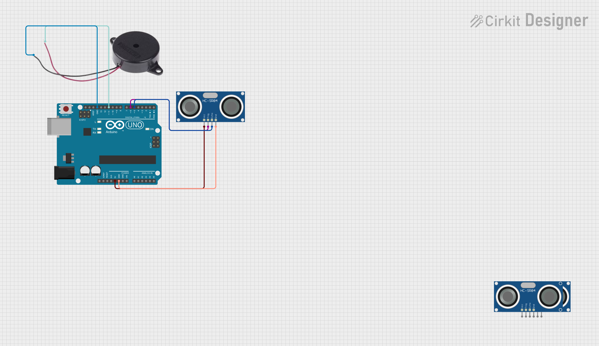
This circuit integrates an Arduino UNO microcontroller with an HC-SR04 Ultrasonic Sensor and a Buzzer. The Arduino UNO is used as the central processing unit to control the sensor and the buzzer. The HC-SR04 Ultrasonic Sensor is connected to the Arduino to measure distances by emitting ultrasonic waves and receiving the echo. The Buzzer is used to provide an audible alert based on the sensor readings. The circuit is powered by the 5V output from the Arduino UNO.
Component List
Arduino UNO
- Description: A microcontroller board based on the ATmega328P.
- Pins: UNUSED, IOREF, Reset, 3.3V, 5V, GND, Vin, A0-A5, SCL, SDA, AREF, D0-D13.
HC-SR04 Ultrasonic Sensor
- Description: A distance measuring sensor that uses ultrasonic sound waves.
- Pins: VCC, TRIG, ECHO, GND.
Buzzer
- Description: An electromechanical component that produces sound.
- Pins: POSITIVE, NEGATIVE.
Wiring Details
Arduino UNO
- 5V connected to HC-SR04 Ultrasonic Sensor VCC.
- GND connected to HC-SR04 Ultrasonic Sensor GND and Buzzer NEGATIVE.
- D11 connected to Buzzer POSITIVE.
- D6 connected to HC-SR04 Ultrasonic Sensor TRIG.
- D5 connected to HC-SR04 Ultrasonic Sensor ECHO.
HC-SR04 Ultrasonic Sensor
- VCC connected to Arduino UNO 5V.
- TRIG connected to Arduino UNO D6.
- ECHO connected to Arduino UNO D5.
- GND connected to Arduino UNO GND.
Buzzer
- POSITIVE connected to Arduino UNO D11.
- NEGATIVE connected to Arduino UNO GND.
Documented Code
Arduino UNO Code (sketch.ino)
void setup() {
  // put your setup code here, to run once:

}

void loop() {
  // put your main code here, to run repeatedly:

}
Note: The provided code is a template and does not include specific functionality. It should be populated with the setup and loop functions to control the HC-SR04 Ultrasonic Sensor and the Buzzer based on the requirements of the application.