Cirkit Designer
Your all-in-one circuit design IDE
Home /
Project Documentation
Simple LED Circuit with 9V Battery and Resistors
Circuit Documentation
Summary of the Circuit
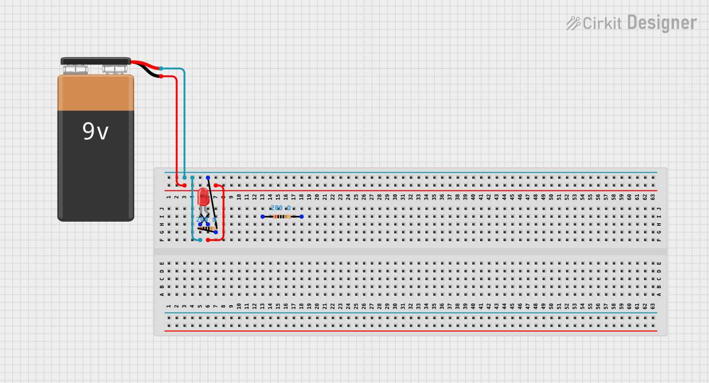
This circuit consists of a simple LED circuit powered by a 9V battery. The circuit includes two resistors, each with a resistance of 200 Ohms, and a red two-pin LED. The LED is connected in series with the resistors and the battery, ensuring that the LED receives an appropriate current to operate without being damaged. The negative terminal of the battery is connected to the cathode of the LED, while the positive terminal is connected to the anodes of the LED through the resistors.
Component List
LED: Two Pin (red)
- Description: A red light-emitting diode (LED) with two pins: an anode and a cathode.
- Pins: cathode, anode
- Purpose: To emit light when powered.
9V Battery
- Description: A standard 9-volt battery with a positive and a negative terminal.
- Pins: -, +
- Purpose: To provide power to the circuit.
Resistor (200 Ohms)
- Description: A resistor with a resistance value of 200 Ohms.
- Pins: pin1, pin2
- Purpose: To limit the current flowing through the LED, protecting it from excessive current.
Wiring Details
LED: Two Pin (red)
- Cathode: Connected to the negative terminal of the 9V battery.
- Anode: Connected to pin2 of one of the 200 Ohm resistors.
9V Battery
- Negative Terminal (-): Connected to the cathode of the red LED.
- Positive Terminal (+): Connected to pin2 of one of the 200 Ohm resistors.
Resistor (200 Ohms)
- Pin1: Not connected in this circuit.
- Pin2: Connected to the positive terminal of the 9V battery and the anode of the red LED.
Documented Code
There is no microcontroller or embedded code associated with this circuit.