Cirkit Designer
Your all-in-one circuit design IDE
Home /
Project Documentation
STM32F103C8T6-Based Adjustable Voltage Sensor
Circuit Documentation
Summary
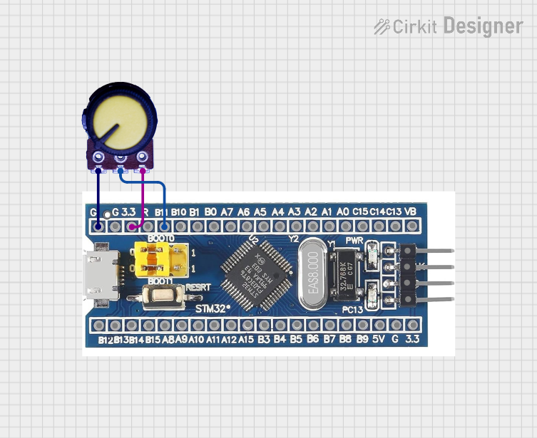
This document provides a detailed overview of a simple circuit consisting of an STM32F103C8T6 microcontroller and a potentiometer. The potentiometer is used to provide an analog input to the microcontroller. The document includes a list of components, wiring details, and any associated code.
Component List
STM32F103C8T6
- Description: A 32-bit ARM Cortex-M3 microcontroller.
- Pins: GND, 3.3V, reset, B11, B10, B1, B0, A7, A6, A5, A4, A3, A2, A1, A0, C15, C14, C13, VBT, 3.3, 5V, B12, B13, b14, B15, A8, A9, A10, A11, A12, A15, B3, B4, B5, B6, B7, B8, B9, SWIO, SWCLK
- Purpose in Circuit: Acts as the main processing unit, reading the analog input from the potentiometer.
Potentiometer
- Description: A variable resistor used to provide an adjustable voltage.
- Pins: GND, Output, VCC
- Purpose in Circuit: Provides an analog voltage to the microcontroller based on its position.
Wiring Details
STM32F103C8T6
- GND: Connected to GND of the Potentiometer.
- 3.3V: Connected to VCC of the Potentiometer.
- B11: Connected to Output of the Potentiometer.
Potentiometer
- GND: Connected to GND of the STM32F103C8T6.
- VCC: Connected to 3.3V of the STM32F103C8T6.
- Output: Connected to B11 of the STM32F103C8T6.
Code
There is no code provided for this circuit.
This document provides a comprehensive overview of the circuit, including the components used, their connections, and any associated code. This should serve as a useful reference for understanding and replicating the circuit.