Cirkit Designer
Your all-in-one circuit design IDE
Home /
Project Documentation
Arduino UNO Controlled Ultrasonic Distance Measurement with LED Indicator
Circuit Documentation
Summary of the Circuit
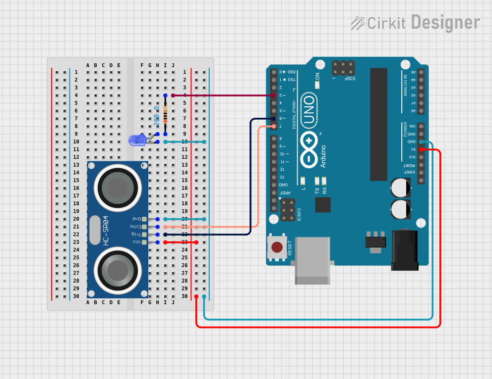
This circuit is designed around the Arduino UNO microcontroller, which serves as the central processing unit. The circuit includes an HC-SR04 Ultrasonic Sensor for distance measurement, a blue LED for indication purposes, and a resistor to limit the current through the LED. The Arduino UNO controls the LED and reads data from the ultrasonic sensor.
Component List
Arduino UNO
- Description: A microcontroller board based on the ATmega328P.
- Pins: UNUSED, IOREF, Reset, 3.3V, 5V, GND, Vin, A0-A5, SCL, SDA, AREF, D0-D13.
- Purpose: Acts as the central controller for the circuit, interfacing with the sensor and controlling the LED.
LED: Two Pin (blue)
- Description: A basic blue light-emitting diode.
- Pins: cathode, anode.
- Purpose: Provides visual indication controlled by the Arduino.
Resistor
- Description: A passive two-terminal electrical component that implements electrical resistance.
- Pins: pin1, pin2.
- Value: 200 Ohms.
- Purpose: Limits the current flowing through the LED to prevent damage.
HC-SR04 Ultrasonic Sensor
- Description: An ultrasonic distance sensor.
- Pins: VCC, TRIG, ECHO, GND.
- Purpose: Measures distances by emitting ultrasonic waves and detecting their reflections.
Wiring Details
Arduino UNO
- D3: Connected to pin2 of the Resistor.
- GND: Shared connection with the cathode of the LED and GND of the HC-SR04 Ultrasonic Sensor.
- D7: Connected to ECHO of the HC-SR04 Ultrasonic Sensor.
- D6: Connected to TRIG of the HC-SR04 Ultrasonic Sensor.
- 5V: Connected to VCC of the HC-SR04 Ultrasonic Sensor.
LED: Two Pin (blue)
- cathode: Connected to GND of the Arduino UNO and GND of the HC-SR04 Ultrasonic Sensor.
- anode: Connected to pin1 of the Resistor.
Resistor
- pin1: Connected to the anode of the LED.
- pin2: Connected to D3 of the Arduino UNO.
HC-SR04 Ultrasonic Sensor
- VCC: Connected to 5V of the Arduino UNO.
- TRIG: Connected to D6 of the Arduino UNO.
- ECHO: Connected to D7 of the Arduino UNO.
- GND: Shared connection with the cathode of the LED and GND of the Arduino UNO.
Documented Code
Arduino UNO Code (sketch.ino)
void setup() {
  // put your setup code here, to run once:

}

void loop() {
  // put your main code here, to run repeatedly:

}
Note: The provided code is a template and does not include specific functionality. It needs to be populated with the setup and loop code to control the LED and interface with the HC-SR04 Ultrasonic Sensor.