Arduino UNO Controlled Robotic Hand with Multiple Servos
Circuit Documentation
Summary of the Circuit
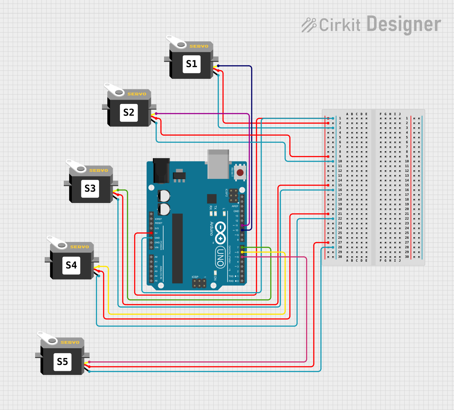
This circuit is designed to control multiple servo motors using an Arduino UNO microcontroller. The Arduino UNO provides power to the servos and sends pulse width modulation (PWM) signals to control the position of the servo arms. The circuit includes six servo motors, each connected to the Arduino UNO for both power and control signals. The embedded code on the Arduino UNO reads analog inputs, maps them to servo positions, and writes the corresponding angles to the servos in a sequential manner.
Component List
Arduino UNO
- Description: A microcontroller board based on the ATmega328P.
- Purpose: Acts as the central controller for the circuit, providing power and control signals to the servo motors.
- Pins: UNUSED, IOREF, Reset, 3.3V, 5V, GND, Vin, A0-A5, SCL, SDA, AREF, D13-D0.
Servo Motors (x6)
- Description: Rotary actuators that allow for precise control of angular position.
- Purpose: To perform mechanical actions as instructed by the Arduino UNO.
- Pins: gnd, vcc, pulse.
Comments (x6)
- Description: Text placeholders for additional information or notes.
- Purpose: To provide context or explanations within the circuit design, not physically present in the circuit.
Wiring Details
Arduino UNO
- 5V: Connected to the VCC of all six servo motors to provide power.
- GND: Connected to the ground (GND) of all six servo motors to complete the power circuit.
- D11: Connected to the pulse pin of the first servo motor.
- D10: Connected to the pulse pin of the second servo motor.
- D7: Connected to the pulse pin of the third servo motor.
- D6: Connected to the pulse pin of the fourth servo motor.
- D5: Connected to the pulse pin of the fifth servo motor.
Servo Motors
- Servo 1:
- vcc: Connected to the 5V pin on the Arduino UNO.
- gnd: Connected to the GND pin on the Arduino UNO.
- pulse: Connected to the D11 pin on the Arduino UNO.
- Servo 2:
- vcc: Connected to the 5V pin on the Arduino UNO.
- gnd: Connected to the GND pin on the Arduino UNO.
- pulse: Connected to the D10 pin on the Arduino UNO.
- Servo 3:
- vcc: Connected to the 5V pin on the Arduino UNO.
- gnd: Connected to the GND pin on the Arduino UNO.
- pulse: Connected to the D7 pin on the Arduino UNO.
- Servo 4:
- vcc: Connected to the 5V pin on the Arduino UNO.
- gnd: Connected to the GND pin on the Arduino UNO.
- pulse: Connected to the D6 pin on the Arduino UNO.
- Servo 5:
- vcc: Connected to the 5V pin on the Arduino UNO.
- gnd: Connected to the GND pin on the Arduino UNO.
- pulse: Connected to the D5 pin on the Arduino UNO.
Documented Code
#include <Servo.h>
// Ligamentos (sensores flexibles)
int L01;
int L02;
int L03;
int L04;
int L05;

// Ángulos (grados del sensor)
int ang01;
int ang02;
int ang03;
int ang04;
int ang05;

// Servos (izquierda a derecha en el circuito)
Servo menique;
Servo anular;
Servo medio;
Servo indice;
Servo pulgar;

void setup()
{
  // Pines PWM como salida
  Serial.begin(9600);
  pinMode(10, OUTPUT);
  pinMode(11, OUTPUT);
  pinMode(7, OUTPUT);
  pinMode(6, OUTPUT);
  pinMode(5, OUTPUT);
}

void loop()
{
  menique.attach(10);
  anular.attach(11);
  medio.attach(7);
  indice.attach(6);
  pulgar.attach(5);

  ang01 = analogRead(10);
  L01 = map(ang01, 767, 964, 0, 270);

  ang02 = analogRead(11);
  L02 = map(ang02, 767, 964, 0, 180);

  ang03 = analogRead(7);
  L03 = map(ang03, 767, 964, 0, 180);

  ang04 = analogRead(6);
  L04 = map(ang04, 767, 964, 0, 180);

  ang05 = analogRead(5);
  L05 = map(ang05, 767, 964, 0, 180);

  delay(2000);
  menique.write(L01);
  delay(2000);
  anular.write(L02);
  delay(2000);
  medio.write(L03);
  delay(2000);
  indice.write(L04);
  delay(2000);
  pulgar.write(L05);
  delay(2000);
}
Filename: sketch.ino
Description: This code initializes five servo objects and attaches them to the corresponding PWM pins on the Arduino UNO. It reads analog values from the same pins (which is likely an error in the code, as analogRead should be used on analog input pins, not PWM output pins), maps these values to a range suitable for servo control, and then writes the mapped values to the servos to set their positions. The servos are actuated sequentially with a delay between each actuation.