
Arduino-Controlled Ultrasonic Water Pump System with LCD Feedback
View and Edit Project In Cirkit Designer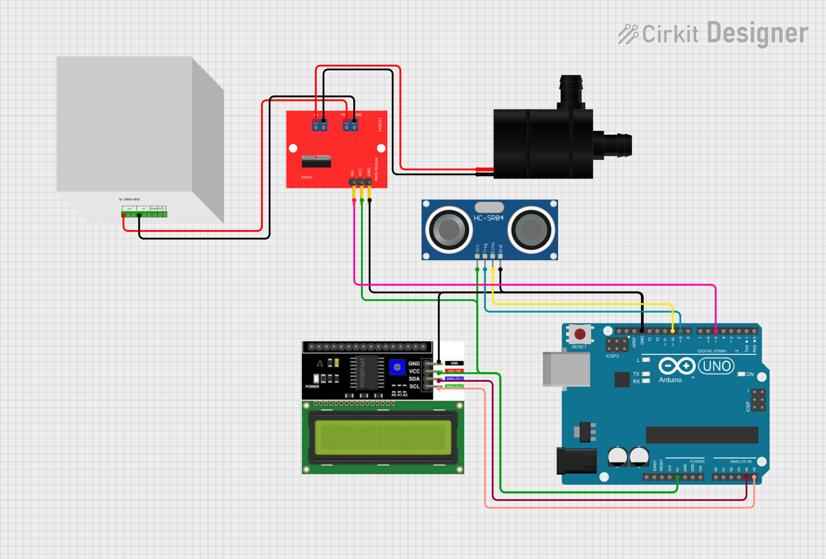
Circuit Documentation
Summary of the Circuit
This circuit is designed to interface an Arduino UNO with an LCD I2C display, an HC-SR04 ultrasonic sensor, and a water pump controlled by a MOS module. The Arduino UNO serves as the central microcontroller unit, managing the input from the ultrasonic sensor and controlling the display and the water pump accordingly. The LCD display is used to show relevant information or readings from the sensor, while the MOS module acts as a switch to control the power to the water pump. The circuit is powered by a 12V DC power supply, which also provides power to the MOS module for driving the water pump.
Component List
Arduino UNO
- Microcontroller board based on the ATmega328P
- It has 14 digital input/output pins, 6 analog inputs, a 16 MHz quartz crystal, a USB connection, a power jack, an ICSP header, and a reset button.
LCD I2C Display
- An alphanumeric liquid crystal display with an I2C interface for easy communication with microcontrollers like the Arduino UNO.
HC-SR04 Ultrasonic Sensor
- A sensor that uses sonar to determine the distance to an object by emitting ultrasonic waves and measuring the time taken for the echo to return.
Water Pump
- A device used to move liquids, such as water, from one place to another. It is typically powered by an electric motor.
MOS Module
- A type of electronic switch that can control the flow of power to a device, such as a water pump, using a signal from a microcontroller.
12V DC Power Supply
- Provides the necessary power to the circuit components. It has multiple voltage outputs and ground connections.
Wiring Details
Arduino UNO
- 5V connected to the VCC pins of the HC-SR04 Ultrasonic Sensor, LCD I2C Display, and MOS Module.
- GND connected to the GND pins of the HC-SR04 Ultrasonic Sensor, LCD I2C Display, and MOS Module.
- A4 (SDA) connected to the SDA pin of the LCD I2C Display.
- A5 (SCL) connected to the SCL pin of the LCD I2C Display.
- D10 connected to the ECHO pin of the HC-SR04 Ultrasonic Sensor.
- D9 connected to the TRIG pin of the HC-SR04 Ultrasonic Sensor.
- D5 connected to pin1 of the MOS Module.
LCD I2C Display
- GND connected to the GND of the Arduino UNO.
- VCC connected to the 5V of the Arduino UNO.
- SDA connected to the A4 (SDA) of the Arduino UNO.
- SCL connected to the A5 (SCL) of the Arduino UNO.
HC-SR04 Ultrasonic Sensor
- VCC connected to the 5V of the Arduino UNO.
- TRIG connected to the D9 of the Arduino UNO.
- ECHO connected to the D10 of the Arduino UNO.
- GND connected to the GND of the Arduino UNO.
Water Pump
- VCC connected to pin7 of the MOS Module.
- GND connected to pin6 of the MOS Module.
MOS Module
- pin1 connected to the D5 of the Arduino UNO.
- pin2 connected to the 5V of the Arduino UNO.
- pin3 connected to the GND of the Arduino UNO.
- pin4 connected to the -V1 of the 12V DC Power Supply.
- pin5 connected to the +V1 of the 12V DC Power Supply.
- pin6 connected to the GND of the Water Pump.
- pin7 connected to the VCC of the Water Pump.
12V DC Power Supply
- -V1 connected to pin4 of the MOS Module.
- +V1 connected to pin5 of the MOS Module.
Documented Code
Arduino UNO Code (sketch.ino)
void setup() {
  // put your setup code here, to run once:

}

void loop() {
  // put your main code here, to run repeatedly:

}
Additional Notes (documentation.txt)
No additional code documentation was provided for the Arduino UNO.