
Arduino UNO Controlled Robot with Bluetooth and Servo Motors
View and Edit Project In Cirkit Designer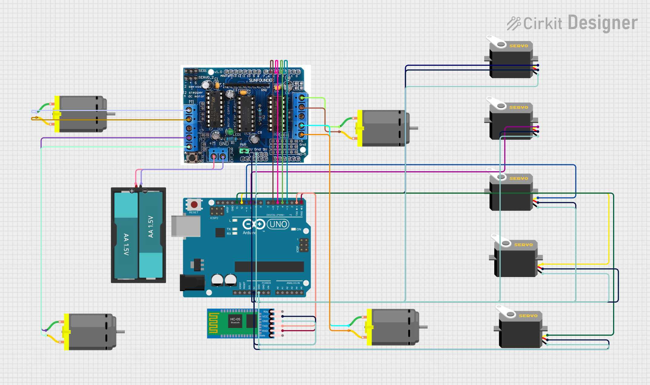
Circuit Documentation
Summary
This circuit is designed to control multiple servo motors and DC motors using an Arduino UNO microcontroller and an L293D motor driver shield. It also includes an HC-05 Bluetooth module for wireless communication. The circuit is powered by a 3V battery pack consisting of two AA batteries.
Component List
Microcontroller
- Arduino UNO: A microcontroller board based on the ATmega328P, with a variety of digital and analog I/O pins.
Motors
- Servo: Four servo motors that can be precisely controlled by sending a PWM signal on their control line.
- DC Motor: Four DC motors that are driven by the L293D motor driver shield.
Communication Module
- HC-05 Bluetooth Module: A wireless communication module that allows the Arduino to communicate with other Bluetooth-enabled devices.
Motor Driver
- L293D Driver Shield: A motor driver shield that mounts on top of the Arduino UNO and provides easy connections for driving DC motors and servos.
Power Supply
- Battery AAx2 3V: A battery pack providing a 3V power supply to the motor driver shield.
Wiring Details
Arduino UNO
- 5V: Connected to the 5V power line that powers the servos and the HC-05 Bluetooth module.
- GND: Connected to the ground line shared by all components.
- D13-D9: Control lines for the servo motors.
- D6-D3: Control lines for the DC motors via the L293D driver shield.
- D1 (TX): Transmit pin connected to the RXD pin of the HC-05 Bluetooth module.
- D0 (RX): Receive pin connected to the TXD pin of the HC-05 Bluetooth module.
Servo Motors
- VCC: Connected to the 5V power line.
- GND: Connected to the ground line.
- Pulse: Each servo has its pulse line connected to a unique digital pin on the Arduino UNO for control.
DC Motors
- Pin 1 & Pin 2: Each DC motor has two pins connected to the L293D driver shield for control.
HC-05 Bluetooth Module
- VCC: Connected to the 5V power line.
- GND: Connected to the ground line.
- TXD: Connected to the RX pin (D0) of the Arduino UNO.
- RXD: Connected to the TX pin (D1) of the Arduino UNO.
L293D Driver Shield
- 5V & GND: Power supply lines connected to the 5V and ground lines, respectively.
- M1-M4: Output lines for controlling the DC motors.
- M+ & GND: Power input lines connected to the 3V battery pack.
Battery AAx2 3V
- VCC: Connected to the M+ line of the L293D driver shield.
- GND: Connected to the ground line of the L293D driver shield.
Documented Code
Arduino UNO Code (sketch.ino)
void setup() {
  // put your setup code here, to run once:

}

void loop() {
  // put your main code here, to run repeatedly:

}
This code is a template for the Arduino UNO. The setup() function is called once when the microcontroller is powered on or reset. It is used to initialize the digital pins as input or output and to set up any other initial conditions. The loop() function is called repeatedly and contains the main logic of the program. It is where the microcontroller reads sensors, controls motors, communicates with other devices, etc.
The actual implementation details would be added to the setup() and loop() functions based on the specific requirements of the circuit's operation. This would typically include setting the servo control pins as outputs and initializing the Bluetooth module, among other tasks.