
ESP32-Controlled LED Dot Display with Level Shifting and Buck Conversion
View and Edit Project In Cirkit Designer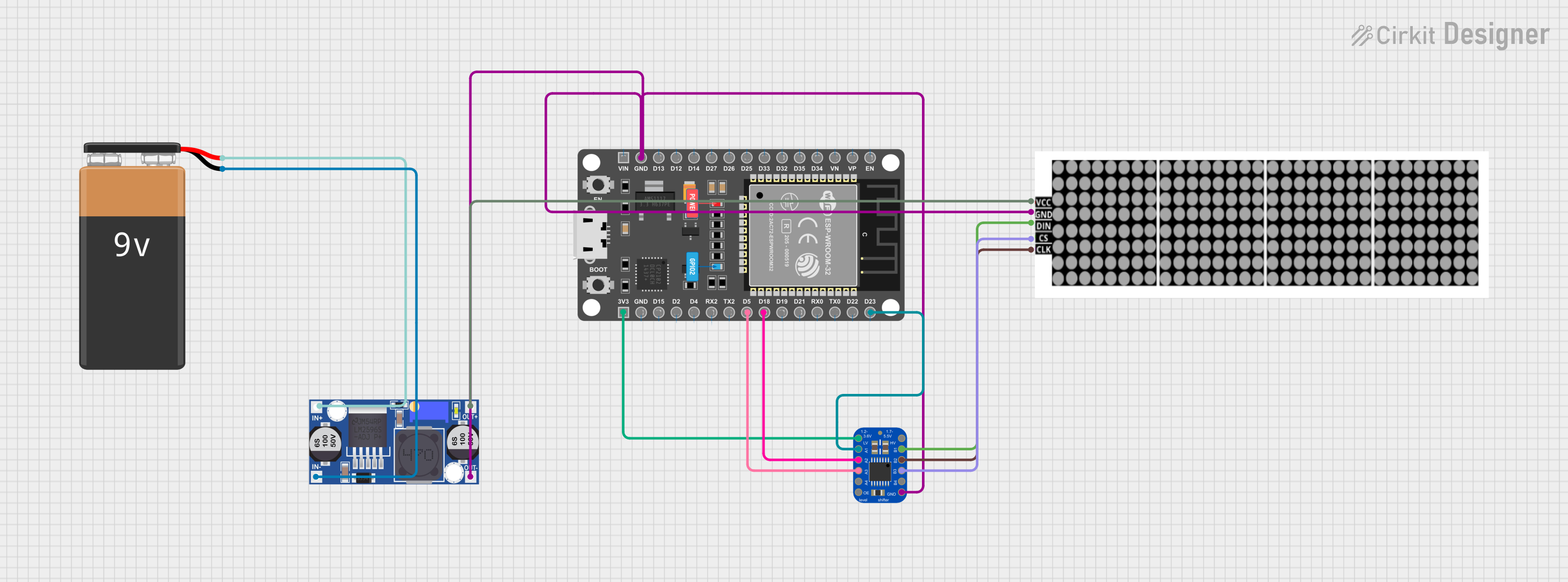
Circuit Documentation
Summary
This circuit is designed to power and control an LED dot display using an ESP32 microcontroller. The circuit includes a 9V battery as the power source, which is stepped down to a lower voltage using a buck converter. The ESP32 microcontroller interfaces with the LED dot display through a level shifter, which ensures that the signal voltages are compatible between the two devices.
Component List
9V Battery
- Description: A standard 9V battery used as the power source for the circuit.
LED Dot Display
- Description: A display module for showing patterns or information, driven by the ESP32 microcontroller.
Buck Converter
- Description: A DC-DC converter that steps down the voltage from the 9V battery to a lower voltage suitable for the LED dot display and the microcontroller.
ESP 32 DEVKIT V1 (30 pins)
- Description: A microcontroller with WiFi and Bluetooth capabilities, used to control the LED dot display.
Adafruit TXB0104 4-channel Bi-Directional Level Shifter
- Description: A device that safely steps up or down signal voltages between different logic levels, allowing for communication between the ESP32 and the LED dot display.
Wiring Details
9V Battery
- Connections:
- Positive terminal connected to the "IN+" pin of the Buck Converter.
- Negative terminal connected to the "IN-" pin of the Buck Converter.
LED Dot Display
- Connections:
- "VCC" connected to the "OUT+" pin of the Buck Converter.
- "GND" connected to the common ground net.
- "DIN" connected to "B1" pin of the Level Shifter.
- "CS" connected to "B3" pin of the Level Shifter.
- "CLK" connected to "B2" pin of the Level Shifter.
Buck Converter
- Connections:
- "IN+" and "IN-" connected to the respective terminals of the 9V Battery.
- "OUT+" connected to the "VCC" pin of the LED Dot Display.
- "OUT-" connected to the common ground net.
ESP 32 DEVKIT V1 (30 pins)
- Connections:
- "GND" connected to the common ground net.
- "3V3" connected to "LV" pin of the Level Shifter.
- "D5" connected to "A3" pin of the Level Shifter.
- "D18" connected to "A2" pin of the Level Shifter.
- "D23" connected to "A1" pin of the Level Shifter.
Adafruit TXB0104 4-channel Bi-Directional Level Shifter
- Connections:
- "GND" connected to the common ground net.
- "LV" connected to "3V3" pin of the ESP32.
- "HV" not explicitly connected in the provided net list.
- "B1", "B2", "B3" connected to "DIN", "CLK", "CS" pins of the LED Dot Display respectively.
- "A1", "A2", "A3" connected to "D23", "D18", "D5" pins of the ESP32 respectively.
- "OE" not explicitly connected in the provided net list.
Documented Code
sketch.ino
void setup() {
  // put your setup code here, to run once:

}

void loop() {
  // put your main code here, to run repeatedly:

}
documentation.txt
(No code provided for documentation.txt)
Note: The code provided for the ESP32 microcontroller is a template with empty setup and loop functions. To control the LED dot display, the user must implement the necessary initialization and control logic within these functions. Additionally, the wiring details for the "HV" and "OE" pins of the level shifter are not provided in the net list and should be addressed according to the specific requirements of the application.